Wheatstone bridge
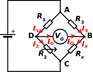
A Wheatstone bridge is an electrical circuit used to measure unknown resistances by balancing the arms of the bridge. These are made up of four resistors that form a closed circuit, one of them being the resistance under measure.
The English physicist and inventor Charles Wheatstone (1802-1875) is best known for being the first to apply the electrical circuit that bears his name (Wheatstone bridge) to measure resistance. It had actually been previously designed by Samuel Hunter Christie in 1832, so Wheatstone's role was to improve and popularize it, beginning in 1843.
Description
In the diagram on the right we have Rx, which is the resistance whose value we want to determine; R1, R2 and R3 are resistors of known values, and resistor R2 is adjustable for set the balance point. If the ratio of the two resistances of the known arm (R1/R2) is equal to the ratio of the two of the unknown arm (R3/Rx), the voltage between points D and B will be zero and no current will flow through the galvanometer V G. In case of imbalance, the direction of the current in the galvanometer indicates whether R2 is too high or too low. The voltage value of the power supply (Vs) is irrelevant and does not affect the measurement.
To carry out the measurement, the resistance R2 is varied until reaching the equilibrium point.
Zero current detection can be done with high precision using the VG galvanometer.
In equilibrium condition it is always fulfilled that:
- R2R1=RXR3⇒ ⇒ RX=R2R1⋅ ⋅ R3{displaystyle {begin{aligned}{frac {R_{2}}}{R_{1}}}}}}}{R_{X}}{R_{3}}}}{R_{3}}}}{Rightarrow R_{X}{frac {R_{2}{R_{1}{1}{1}{1}{1}{1}{1⁄4pt}{1}}{cd}}{1}}}{1}{1}{1}{1}{1}{1}}{1}{1}{1}{1}}}{1}{1st}}}}}{1st}{1st}{1st}{1st}
When the bridge is built such that R3 equals R1, Rx equals R2 in equilibrium condition (zero current through the galvanometer).
If the values of R1, R2, and R3 are known very precisely, the value of Rx can be equally precisely determined. Small changes in the value of Rx will break the equilibrium and will be clearly detected by the galvanometer indication.
Alternatively, if the values of R1, R2 and R3 are known and R2 is not adjustable, the current through the galvanometer can be used to calculate the value of Rx, this procedure being faster than zeroing the current through the meter.
Demo
First we use Kirchhoff's current law (KCL) to find the current flowing in nodes D and B (IG):
Node D:
- I1− − I2− − IG=0{displaystyle {begin{aligned}I_{1}-I_{2}-I_{G} alien=0end{aligned}}}}}}
Node B:
- I3− − IX+IG=0{displaystyle {begin{aligned}I_{3}-I_{X}+I_{G} alien=0end{aligned}}}}}}
Then we use Kirchhoff's voltage law (KVL) to find the voltages of the meshes ABD and BCD:
ABD Mesh:
- V3− − VG− − V1=0⇒ ⇒ (I3⋅ ⋅ R3)− − (IG⋅ ⋅ RG)− − (I1⋅ ⋅ R1)=0{displaystyle {begin{aligned}V_{3}-V_{G}-V_{1} alien=0\Rightarrow (I_{3}cdot R_{3})-(I_{G}cdot R_{G})-(I_{1}cdot R_{1}{1}) stranger=0end{al}
BCD Mesh:
- VX− − V2− − VG=0⇒ ⇒ (IX⋅ ⋅ RX)− − (I2⋅ ⋅ R2)− − (IG⋅ ⋅ RG)=0{displaystyle {begin{aligned}V_{X}-V_{2}-V_{G} alien=0\Rightarrow (I_{X}cdot R_{X})-(I_{2}cdot R_{2})-(I_{G}cdot R_{G) stranger=0end{aligned}
When the bridge is balanced, then IG = 0, then the second set of equations can be rewritten as:
- I3⋅ ⋅ R3=I1⋅ ⋅ R1IX⋅ ⋅ RX=I2⋅ ⋅ R2{displaystyle {begin{aligned}I_{3}cdot R_{3}{I_{1}{1}{1}cdot R_{1}I_{X}cdot R_{X}{x}{x1}{2}{2}}}{aligned}}}}
So, dividing the equations and rearranging, you get:
- I3I1=R1R3{displaystyle {I_{3} over {I_{1}}}}{{{{R_{1}} over {R_{3}}}}}}}}
- IXI2=R2RX{displaystyle {I_{X} over {I_{2}}}}{{{{R_{2}} over {R_{X}}}}}}}}
Again, if IG = 0, then I 3 = IX and I1 = I2.
such that:
I3I1=IXI2{displaystyle {I_{3} over {I_{1}}}}{{{I_{X} over {I_{2}}}}}}}}}
then:
R2RX=R1R3{displaystyle {R_{2} over {R_{X}}}}={{{R_{1} over {R_{3}}}}}}
Clearing, we obtain that the desired value of RX to achieve equilibrium is:
- RX=R3⋅ ⋅ R2R1{displaystyle R_{X}={{R_{3}cdot R_{2}} over {R_{1}}}}}
If we know the values of the four resistors and the power supply (VS), and the resistance of the galvanometer is high enough so that IG is negligible, the voltage across the galvanometer (VG) can be determined by working with the voltage of each voltage divider by subtracting them from each other. The resulting equation is:
- VG=(R2R1+R2− − RXRX+R3)VS=0,substituteRX{displaystyle V_{G}=left({R_{2} over {R_{1+R_{2}}}}-{R_{X} over {R_{X}+R_{3}}}}}}}{right)V_{S}=0,{text{ when replacing }R_{X}}}}
where VG is the voltage between nodes D and B.
Variants
Variants of the Wheatstone bridge can be used for the measurement of impedances, capacitances and inductances.
The bridge arrangement is also widely used in electronic instrumentation. To do this, one or more resistances are replaced by sensors, which, when their resistance varies, give rise to an output proportional to the variation. At the exit of the bridge, where the galvanometer is, (VG) is usually placed an amplifier.
The Wheatstone bridge is the fundamental, but there are other variants that can be used to measure different types of resistances when the fundamental Wheatstone bridge is not adequate. Some of those variants are:
- Carey Foster Bridge, to measure small resistances.
- Kelvin Bridge, to measure small resistances of four terminals.
- Maxwell Bridge, to measure impedances.
- Hay Bridge for inductance measurement.
- Bridge of Wien
Electronic scale
The Wheatstone bridge is widely used in electronic balances based on Strain Gauge, the objective of these devices is to measure an output voltage proportional to the variation of the weight supported on it.
Contenido relacionado
Irene Joliot-Curie
Potentiometry
Trans siberian

![{displaystyle {begin{aligned}{frac {R_{2}}{R_{1}}}&={frac {R_{X}}{R_{3}}}\[4pt]Rightarrow R_{X}&={frac {R_{2}}{R_{1}}}cdot R_{3}end{aligned}}}](https://wikimedia.org/api/rest_v1/media/math/render/svg/38ffdada25fef2bca61d0c2b35c6e5bdbda190a5)


