Switching circuit
In electricity and electronics, the laws of Boolean algebra and binary logic can be studied using switching circuits. A commutation circuit will be made up of a series of contacts that will represent the input logic variables and one or several loads that will represent the output logic variables or functions.
 |  |  |  |  |  |  |  |
 |  |  |  |  |  |  |  |
 |  |  |  |  |  |  |  |
The contacts can be normally open (NO) or normally closed (NC). The first ones will remain open as long as no action is taken on them (for example when pressing a switch, saturating a transistor, etc.). NC contacts will work just the opposite. This means that if you act on a NO contact it will close and if you do it on a NC it will open.
Basics
 |
 |
The switching circuits are based on switches that allow or do not allow the circulation of an electric current, these switches can be manual if they are acted directly, like a light switch, for example; electrical: relays or contactors, if their action is electro-mechanical, or electronic, transistors or logic gates, if they are based on electronic technology.
For simplicity, we will represent a switch by its electrical contacts, if a switch connects two points a and b, we will say that it is open if it does not allow electrical circulation between those two points: a and b. We will say that it is closed if it allows electrical circulation between those two points.
 |
 |
We will say that a switch is normally open (NO) if when it is not acted upon it is open, the normal position is also called rest position, which the switch will normally have due to the action of a spring that leads to that position.
When a normally open (NO) switch is actuated, the switch closes, allowing electrical flow through it.
Overcoming the force exerted by the spring or spring, and giving rise to electrical contact between its terminals.
The figure shows a normally open pushbutton, at rest in the upper part, with the spring at rest and its contacts separated, in the lower part that same pushbutton is seen actuated, with the spring compressed and its electrical terminals in contact, allowing electrical circulation between points a and b.
 |
 |
If between two points a and b, we place a normally closed (NC) switch, which is closed when it is not acted upon, in this case, the relaxation of the spring or spring leads to contact the electrical terminals of the switch, allowing electrical circulation through it, the switch is closed. If we act on it overcoming the action of the spring, separating the contacts, the switch opens, not allowing electrical circulation. In these switches the result is the opposite of the action, if we act on the switch the switch opens, cutting off the flow of electrical current, if we do not act on it, it closes allowing electrical circulation.
 |  |
 |  |
As we have seen, the switches can be actuated manually, or mechanically by limit switches, pressure switches or other elements that, based on an external action, lead to an electrical connection or disconnection.
But a circuit can act on another circuit, through relays or contactors, so that we can have a switching circuit, the result of which is the action on another circuit, in these cases the presence or not of an electric current gives rise to to the modification of the state of a switch, which will go from its rest position to that of actuated.
In the figure we can see a series of switches of this type. The action on them is done by means of a solenoid, which generates a magnetic field and which moves the ferromagnetic core of the armature, defeating the spring, and changing the electrical contacts. When the electric current does not act, the spring raises the switch to the rest position.
Representation agreement
 |  |  |  |  |
 |  |  |  |  |
 |  |  |  |  |
 |  |  |  |  |
In a commutation circuit, an analysis of the logic of the circuit is carried out, abstracting from the operating details of the mechanisms involved, as well as the sizing of the devices and the rest of the circuit for current intensities and difference in potential with which it works, paying priority attention to the logic of the commutation, for this reason, some of the electrical details, typical of electrical circuits, are not necessary, and if it is necessary to determine an agreement for the representation of the circuits that prevents errors in its interpretation, taking into account the following:
- Switching circuit, is a operating scheme and not a building plane, therefore the situation of the apparatuses will be made according to that logic.
- Electrical details, such as intensities or electrical tensions, are not indicated in a switch circuit.
- The appliances are always represented in their resting position, even if they are connected directly to a power source.
- The performance of the switches is always from top to bottom, the rest position is the highest and the lowest performance.
Components for a switch circuit.
 |  |  |
 |  |  |
 |  |  |
| Figure 1 |
The following conventions should be taken into account (see Figure 1):
- A NA contact represents a switchable variable
- An NC contact represents a negated logical variable (A').
- A closed circuit is considered a logical one (1).
- An open circuit is considered a logical zero (0).
- If you do not act on a contact you consider that the variable you represent is 0.
- If you act on a contact you consider that the variable you represent is 1.
- If the charge is not excited the function is considered 0 (for example a lamp off).
- If the load is excited the function is considered 1 (light on).
Multi Switch
 |  |  |
 |  |  |
 |  |  |
| Figure 2 |
A multiple switch, is the one that with only one command moves several contacts simultaneously, this type of switch, not so simple, is used to switch several circuits at the same time, electively separated.
This type of switch can have direct and inverse contacts, in the figure the first two are direct and the third inverse, which in turn can be of different section, depending on the intensity of current that flows through each of them.
The Relay
 |  |  |
 |  |  |
 |  |  |
A relay or Contactor is an electrically controlled automatic switch, in this way an electrical signal gives rise to new contacts that, in turn, feed or stop feeding other circuits.
In the figure, you can see the schematic representation of a relay. The contacts are represented at rest, in the position they would have when the coil is not powered; when it receives voltage, the armature moves, changing the position of the contacts.
Series Circuit
 |  |  |  |
| Figure 3 |
In this way, Figure 3 represents the logical function AND (AND), that is, L=a·b·...·n. According to the truth table of this function, the circuit is closed only if each of the switches involved is closed.
Parallel circuit
 |  |  |
 |  | |
 |  |  |
 |  |  |
| Figure 4 |
In the same way, Figure 4 represents the logical function OR (OR), that is, L= a+b+... +n; and according to his truth table, the circuit is closed if at least one of the switches is closed.
Switch
 |  |  |
 |  |  |
| Figure 5 |
The switch is made up of a direct switch and a reverse switch, see Figure 5, which act together, so that with a single action one circuit is isolated and another is connected, switching the two circuits.
In the figure you can see that the connection on the left is connected to the bottom on the right when a is not actuated.
If a is activated, the output is through the upper connection on the right.
 |  |  |  |  |
 |  |  |  |  |
| Figure 6 |
Two switches connected according to Figure 6, results in a circuit, which is alternately open or closed, just by modifying one of the two switches, if both are in the same position the circuit is connected, if it is modified Any one of the two is disconnected, which will reconnect when acting on one of them, regardless of which one. This circuit is commonly used for lighting on stairwells or operation from two different points. It is also called three way or three ways.
Crossover switch
 |  |  |  | ||
| a{displaystyle a,} |  |  |  |  | c{displaystyle c,} |
 |  |  |  | ||
| b{displaystyle b,} |  |  |  |  | d{displaystyle d,} |
| Figure 7 | |||||
 |  |  |  | ||
| a{displaystyle a,} |  |  |  |  | c{displaystyle c,} |
| b{displaystyle b,} |  |  |  |  | d{displaystyle d,} |
 |  |  |  | ||
| Figure 8 |
A crossover switch swaps the two input lines (a, b) with the two output lines (c, d), in figures 7 and 8, you can see two equivalent diagrams of this type of switch.
In one position a is connected with c and b with d and in the other they are interchanged connecting a with d and c with b.
In these two figures it can be seen perfectly that different distributions of the devices and different wiring can give rise to the same results.
Electromechanical oscillator
 |  |  |  |
 |  |  |  |
The construction of an Oscillator, with exclusively electromechanical means, is done simply, connecting the coil of a relay to one of its normally connected contacts (NC), when the relay is excited, the contact (NC) is disconnected, disconnecting the coil, which causes the (NC) contact to make contact again.
This is the mechanism on which the classic electric doorbell is based.
Combinational system
In automata theory, a combinational system is a logical system based on Boolean algebra, both in electronic and electromechanical technology. We can see an implementation in switches of combinational systems, ordering by the number of variables involved.
Number of combinations
Starting with a number n of variables, each of which can take the value true: 1, or false: 0, By combinatorics, we can know that the total number of combinations: C, that can occur is:
- C=2n{displaystyle C=2^{n}}
the number of combinations that can be given with n variable, each of which can take one of two logical values is two to the power of n, that is, the number of combinations: C, grows exponentially with respect to the number of variables n:
- nC01122438416532...... ...... n2n{displaystyle {begin{array}{r presumption}n fakeC\\hline 0 fake11}{1}{1}{2}{3}{4}{4}{4}{4}{4}{5 fakeC\\\ldots &\ldots\\ldots \\\\n supposed}{n supposed}{n supposed}{n supposed}{n supposed}{n supposed}{end{n supposed}{end{end{end{end{n}{n}{end{array}}}}}}}}}}}}}}}}}}}}}}}}}}}}}}}}
If we consider that a combinational system of n binary variables, it can present a true result: 1, or false: 0 , for each of the possible input combinations we have that a number of functions can be constructed: F with n input variables, where:
- F=2C=22n{displaystyle F=2^{C}=2^{2^{n}}}}
Which results in the following table:
- nF02142163256465.53654.294.967.296...... ...... n22n{displaystyle {begin{array}{r presumption}n strangerF\\\hline 0 fake21}{42}{2}{4}{4}{.}5365 pretend4_{.}294.967.296\ldots \ldots \n age2^{2{nx}{nx1}{nx1}{nx1}{nx1}{nx1}{nx1}{nx1}{nx1}{nxx1}{nxx1}{nx1}{nx1}{nxx1}{nx1}{nx1}{nx1nx1nx1}{nx1nx1nx1}{nx1nxx1nx1nx1nx1nx1nx1}{nx1}{
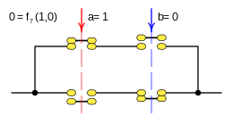
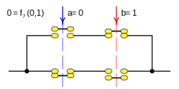
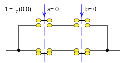
To compose a truth table, we will put the n variables in a horizontal line, below these variables we develop the different combinations that can be formed with 1 and 0, giving rise to the different C, number of combinations. Normally only the function for which the truth table is made is represented, and in any case partial functions that help in its calculation, in the figure, you can see all the possible functions F, which can given for the given number of variables.
So we can see that for two binary variables: a and b, n= 2 that can take the values 1 and 0, four combinations can be developed: C= 4, with these values sixteen different results can be defined, F= 16, each of which would be a function of two binary variables. For another number of variables, the corresponding results will be obtained, given the exponential growth of F, when n takes values greater than four or five, the representation in a table is complex, and if one wants to represent the possible combinations F, it is already complex for n= 3.
Truth table of zero variables
- ♪
- C= 1
- F=2
- ⋅ ⋅ f1f2⋅ ⋅ 10{displaystyle {begin{array}{cUDcccccccccccccccccccccccc}cdot &f_{1}{1}{2}\hline cdot >}{end{array}}}}}}
Case: 1. x = F one ( ) {displaystyle x=f_{1}()}
This function is called a tautology and returns the true result (1) in all cases.
This function is rendered:
- f1()=1{displaystyle f_{1}();=1}
These functions are equivalent:
- f1(){displaystyle top quad longleftrightarrow quad f_{1}()}
Case: 2. x = F 2 ( ) {displaystyle x=f_{2}()}
This function is called a contradiction and returns false(0) in all cases.
This function is rendered:
- f2()=0{displaystyle f_{2}();=;0}
These functions are equivalent:
- f2(){displaystyle bot quad longleftrightarrow quad f_{2}()}
Truth table of a variable
- #1
- C= 2
- F=4
- af1f2f3f41110001010{displaystyle {begin{array}{c meantcccccccccccccccccccccccccccccccccccccccccc}a fakef_{1}{1}{1}{1}{1}{4}{4}{\\hline 1 fake1}{1 fake0}{0{0}{0}{0}{0}{0}{0}{0}{0}{0}{0}{0}{0}}}}}}}}}}}}}}}}}}}}}}}}}}}}}}}}}}}}}}}}}}}}}}}}}}}}}}
Case: 1. x = F one ( a ) {displaystyle x=f_{1}(a)}
This function is called a tautology and returns the true result (1) in all cases.
This function is rendered:
- f1(a)=1{displaystyle f_{1}(a);=;1}
These functions are equivalent:
- f1() f1(a){displaystyle top quad longleftrightarrow quad f_{1}()quad longleftrightarrow quad f_{1}(a)}
Case: 2. x = F 2 ( a ) {displaystyle x=f_{2}(a)}
This function is called: logical statement, assigns the function the same logical value as the variable.
This function is rendered:
- f2(a)=a{displaystyle f_{2}(a);=;a}
Case: 3. x = F 3 ( a ) {displaystyle x=f_{3}(a)}
This function is called: logical negation, it assigns to the function the opposite logical value to that of the variable.
This function is rendered:
- f3(a)=¬ ¬ a=a! ! {displaystyle f_{3}(a);=neg a;=;{bar {a}}}}
Case: 4. x = F 4 ( a ) {displaystyle x=f_{4}(a)}
This function is called a contradiction and returns false(0) in all cases.
This function is rendered:
- f4(a)=0{displaystyle f_{4}(a);=;0}
These functions are equivalent:
- f2() f4(a){displaystyle bot quad longleftrightarrow quad f_{2}()quad longleftrightarrow quad f_{4}(a)}
Truth table of two variables
- #2
- C=4
- F= 16
- abf1f2f3f4f5f6f7f8f9f10f11f12f13f14f15f16111111111100000000101111000011110000011100110011001100001010101010101010{1}{1}{1}{1}{1}{1}{4}{1}{1}{1}{1}{1}{1}{1}{1}{1}{1}{1}{1}{1}{1}{0}{1}{1}{1}{1}{0}{1}{1}{1}{1}{1}{1}{1}{1}{1}{0}{1}{1}{1}{1}{1}{1}{1}{1}{0}{1}{1}{1}{1}{1}{1}{1}{1}{1}{1}{1}{1}{1}{1}{1}{1}{1}{1}{1}{1}{1}{1}{1}{1}{1}{1}{1}{1}{1}{1}{1}{1}{1}{1}{1}{1}{1}{1}{1}{
Case: 1. x = F one ( a b ) {displaystyle x=f_{1}(a,b)}
This function is a tautology and returns true(1) in all cases.
This function is rendered:
- f1(a,b)=1{displaystyle f_{1}(a,b);=;1}
These functions are equivalent:
- f1() f1(a) f1(a,b){displaystyle top quad longleftrightarrow quad f_{1}()quad longleftrightarrow quad f_{1}(a)quad longleftrightarrow quad f_{1}(a,b)}
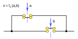
Case: 2. x = F 2 ( a b ) {displaystyle x=f_{2}(a,b)}
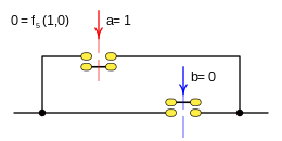
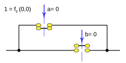
This function is called: Logical disjunction, and it presents the result false(0) only when the two variables a: a, b; are false(0).
This function is rendered:
- f1(a,b)=a b=a b=a+b{displaystyle f_{1}(a,b);=;alor b;=;aoplus b;=;a+b}
Case: 3. x = F 3 ( a b ) {displaystyle x=f_{3}(a,b)}
This function is rendered:
- f3(a,b)=a← ← b{displaystyle f_{3}(a,b);=;aleftarrow b}
Case: 4. x = F 4 ( a b ) {displaystyle x=f_{4}(a,b)}
This function is rendered:
- f4(a,b)=a{displaystyle f_{4}(a,b);=;a}
These functions are equivalent:
- f2(a) f4(a,b){displaystyle f_{2}(a)quad longleftrightarrow quad f_{4}(a,b)}
Case: 5. x = F 5 ( a b ) {displaystyle x=f_{5}(a,b)}
This function is rendered:
- f5(a,b)=a→ → b{displaystyle f_{5}(a,b);=;arightarrow b}
Case: 6. x = F 6 ( a b ) {displaystyle x=f_{6}(a,b)}
This function is rendered:
- f6(a,b)=b{displaystyle f_{6}(a,b);=;b}
These functions are equivalent:
- f2(b) f6(a,b){displaystyle f_{2}(b)quad longleftrightarrow quad f_{6}(a,b)}
Case: 7. x = F 7 ( a b ) {displaystyle x=f_{7}(a,b)}
This function is rendered:
- f7(a,b)=a▪ ▪ b{displaystyle f_{7}(a,b);=;aleftrightarrow b}
Case: 8. x = F 8 ( a b ) {displaystyle x=f_{8}(a,b)}
This function is rendered:
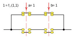
- f8(a,b)=a∧ ∧ b=aΔ Δ b=a⋅ ⋅ b=ab{displaystyle f_{8}(a,b);=;aland b;=;aodot b;=;acdot b;=;a,b}
Case: 9. x = F 9 ( a b ) {displaystyle x=f_{9}(a,b)}
This function is rendered:
- f9(a,b)=a↑ ↑ b{displaystyle f_{9}(a,b);=;auparrow b}
Case: 10. x = F 10 ( a b ) {displaystyle x=f_{10}(a,b)}
This function is rendered:
- f10(a,b)=a b{displaystyle f_{10}(a,b);=;anleftrightarrow b}
Case: 11. x = F eleven ( a b ) {displaystyle x=f_{11}(a,b)}
This function is rendered:
- f10(a,b)=¬ ¬ b=b! ! {displaystyle f_{10}(a,b);=neg b;=;{bar {b}}}}
These functions are equivalent:
- f3(b) f11(a,b){displaystyle f_{3}(b)quad longleftrightarrow quad f_{11}(a,b)}
Case: 12. x = F 12 ( a b ) {displaystyle x=f_{12}(a,b)}
This function is rendered:
- f10(a,b)=a b=a− − b{displaystyle f_{10}(a,b);=;anrightarrow b;=;a-b}
Case: 13. x = F 13 ( a b ) {displaystyle x=f_{13}(a,b)}
This function is rendered:
- f13(a,b)=¬ ¬ a=a! ! {displaystyle f_{13}(a,b);=neg a;=;{bar {a}}}}
These functions are equivalent:
- f3(a) f13(a,b){displaystyle f_{3}(a)quad longleftrightarrow quad f_{13}(a,b)}
Case: 14. x = F 14 ( a b ) {displaystyle x=f_{14}(a,b)}
This function is rendered:
- f10(a,b)=a b=b− − a{displaystyle f_{10}(a,b);=;anleftarrow b;=;b-a}
Case: 15. x = F fifteen ( a b ) {displaystyle x=f_{15}(a,b)}
This function is rendered:
- f10(a,b)=a↓ ↓ b{displaystyle f_{10}(a,b);=;adownarrow b}
Case: 16. x = F 16 ( a b ) {displaystyle x=f_{16}(a,b)}
This function is rendered:
- f16(a,b)=0{displaystyle f_{16}(a,b);=;0}
These functions are equivalent:
- f2() f4(a) f16(a,b){displaystyle bot quad longleftrightarrow quad f_{2}()quad longleftrightarrow quad f_{4}(a)quad longleftrightarrow quad f_{16}(a,b)}
Contenido relacionado
Camera
Civilization (series)
Lossy compression algorithm


