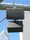
Speaker
A loudspeaker (also known as a speaker, loudspeaker, horn, or horn >, mostly in South America) is an electroacoustic transducer, that is, a device that converts an electrical audio signal into mechanical sound waves. A speaker system, generally referred to simply as speaker, includes one or more transducers, a baffle, electrical connections, and possibly includes a crossover. The transducer can be seen as a linear motor connected to a diaphragm that couples the movement of the motor to the movement of the air. An audio signal, typically from a microphone, recording, or radio broadcast, is electronically amplified to a power level sufficient to drive the motor, and the motor reproduces the sound corresponding to the original electrical signal. Performs the reverse function of a microphone. Small speakers can be found in radios, televisions, portable music players, and computers. Large loudspeakers are used in high-fidelity powerful sound systems, electronic musical instruments, sound reinforcement systems in cinemas and theaters, and public address systems.
Terminology
The term loudspeaker refers to either individual drivers or a complete speaker system, also referred to as a "cabinet," consisting of a baffle, one or more drivers, and a crossover. In Costa Rica, El Salvador, Honduras, Nicaragua, Peru, Chile and Argentina, the loudspeaker is known as speaker or altoparlante, horn in Mexico, Panama, Colombia and Ecuador —although the meaning of "speaker" and "altoparlante" is understood. For its part, in Venezuela it is known as corneta.
In order to adequately and accurately reproduce a wide range of frequencies, most systems use more than one speaker (transducer), particularly for higher SPL or maximum precision. Individual speakers are used to reproduce different bands of frequencies; called: subwoofer (for very low frequencies); woofer (low frequencies); speaker-mid (medium frequencies); tweeter (high frequencies); and even super tweeter (the highest audible frequencies and beyond). When more than one loudspeaker is used in a system, a crossover is placed to separate the input signal into its various frequency bands and direct them to the appropriate transducer. A loudspeaker with n different frequency bands is defined as a n way loudspeaker. The most common are the 2-way speaker and the 3-way speaker. In what is known as an active speaker, the amplifier is included in the box itself, these are becoming more common, especially as computer speakers.
Basic principles
When a loudspeaker is turned on, its membrane vibrates the air in front of it, but also behind it. In the vibration movement when the membrane advances, the air pressure increases in front, but decreases behind, and vice versa when the membrane recedes: We say that the rear wave is 180 ° out of phase. Therefore, changes in air pressure (sound) are not properly transmitted to the surrounding air, as air tends to flow between the front and back of the membrane to equalize the pressures. This is the so-called acoustic short circuit phenomenon, very significant at low frequencies. The solution is to put a baffle to suppress (or at least attenuate) the rear radiation and not cancel the front ones. In practice, we call the way in which we will manage this problem acoustic loading. Specialists have found a multitude of ways, more or less complex, to solve it. The design of the baffle significantly influences the sound quality obtained.
A loudspeaker system generally contains not only the loudspeakers, but also filters, amplifier modules, power or adjustment buttons, protective grilles or even ventilation ports in the case of a bass-reflex speaker cabinet. . Finally, it is equipped with connectors intended to connect an amplifier or other source that contains the sound signal to be emitted. Some speakers called "wireless" can do without this connection, the signal that arrives through radio transmission (currently the Bluetooth system is the most common for consumer products). Such speakers are often powered by batteries or batteries, making them mobile devices.
There are many types of loudspeaker systems that correspond on the one hand to a wide variety of uses, and on the other hand to different levels of quality, with loudspeakers generally considered to be the weakest link in the sound reproduction chain. along with the listening room. The use that you want to make is, therefore, essential: sound system, monitoring, Hi-Fi or even home theater. Music genre, contrary to popular belief, does not influence the choice of speaker systems. A good quality speaker system must be able to correctly reproduce any type of sound. It is even part of the criteria and techniques for selecting an acoustic box. However, the end use determines the selection criteria, so we will not use the same solutions to distribute music in a supermarket as to provide sound for an outdoor concert.
History
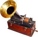
The first device that allowed the general public to listen to music at home was the phonograph, patented by Thomas Edison on December 19, 1877. It was followed by the gramophone invented by Émile Berliner in 1888, which used disc-shaped stands. In these two devices, there is no "speaker" strictly speaking: the sound is emitted by a membrane attached to the needle that is in contact with the support and is only amplified by a horn.
The principle of the acoustic horn consists in performing an impedance match between the emitting membrane and the ambient air. Thus, a spectacular improvement in efficiency is obtained so that the horns continue to be, at least for the medium and high frequencies, used almost universally in the field of power sound reinforcement. For bass, the size of the horn often becomes prohibitive so this solution is still rare, but we must mention Klipsch's Klipschorn speaker, created in the 1940s, which uses a bass horn thanks to taking advantage of of the walls of the room, placed in the corner.
Johann Philipp Reis installed an electric speaker in his telephone in 1861; it was capable of reproducing clear tones, but could also reproduce muffled speech after some revisions. Alexander Graham Bell patented his first electric loudspeaker (capable of reproducing intelligible speech) as part of his telephone in 1876, which was followed in 1877 by an improved version of Werner von Siemens. During this time, Thomas Edison received a British patent for a system using compressed air as the amplification mechanism for his early cylinder phonographs, but ultimately settled on the familiar metal horn driven by a membrane attached to the needle. In 1898 Horace Short patented a design for a loudspeaker driven by compressed air; he then sold the rights to Charles Parsons, who was granted several additional British patents before 1910. A few companies, including the Victor Talking Machine Company and Pathé, produced record players using compressed-air speakers. However, these designs were significantly limited by their poor sound quality and inability to reproduce sound at low volumes. Variants of the system were used for advertising applications, and more recently other variations have been used to test the resistance of space equipment to the very strong sound and vibration levels produced by rocket launches.
Moving coil speaker
The first experimental dynamic (moving coil) loudspeaker was invented by Oliver Lodge in 1898. The first practical moving coil loudspeakers were manufactured by Danish engineers Peter L. Jensen and Edwin Pridham in 1915, in Napa, California. Like earlier loudspeakers, they used horns to amplify the sound produced by a small diaphragm. Jensen was denied the patents. Unsuccessfully trying to sell his product to the telephone companies, in 1915 they switched his tack to radios and public address systems, calling their product Magnavox. Jensen was for years behind the invention of the loudspeaker partly owned by the Magnavox company. But the true beginnings of the moving coil loudspeaker as we know it date back to 1925, when Chester W. Rice and Edward W. Kellogg patented it (U.S. Patent 1,707,570. April 2, 1929), along with an amplifier capable of delivering 1 watt power to your device. The latter, the Radiola Model 104, with a built-in amplifier, was released the following year. The main difference between the earlier attempts and the Rice and Kellogg patent is the tuning of the mechanical parameters to obtain a relatively flat frequency response. We refer to the Rice-Kellogg loudspeaker to designate this early model. However, the paternity is disputed, as similar work has been done in other developed countries.
Early loudspeakers used electromagnets because large, powerful permanent magnets were not available at a reasonable price. The coil of the electromagnet was activated by a current through another pair of connections. This coil had a second function, being used as a choke by filtering the power to the audio amplifier, to which the speaker was connected. The AC ripple in the current was attenuated by passing through the choke. However, the alternating frequencies present in the power supply to the amplifier tended to modulate the audio signal passing through the voice coil, resulting in audible hum. In 1930 Peter L. Jensen introduced the first commercial permanent magnet loudspeaker; however, the heavy iron magnets of the time were impractical, and loudspeakers with electromagnets were predominant until the widespread availability of lightweight alnico magnets became available after World War II.
Loudspeakers still use the same basic principle and have taken their final form fairly quickly, but they have come a long way: the materials used and the design and testing with computerized systems mean that performance has seen considerable progress, even in models for the consumer market.
The first speaker systems
In the 1930s loudspeaker manufacturers began to combine two or three sets of loudspeakers, each optimized for different frequency bands, to improve frequency response and increase sound pressure level. In 1937 The first system commercial for movie theaters, "The Shearer Horn Loudspeaker System for Theaters" a two-way system was introduced by Metro-Goldwyn-Mayer. It used two 15" low-frequency drivers, a 375 Hz crossover, and a single multi-cell horn speaker with two compression drivers for the high frequencies. John Kenneth Hilliard, James Bullough Lansing, and Douglas Shearer were involved in creating the system. At the 1939 New York General Exposition a very large two-way public address system was mounted on a tower in Flushing Meadows. Eight 27" low-frequency amplifiers designed by Rudy Bozak in his role as Cinaudagraph's chief engineer. Along with High Frequency Loudspeakers manufactured by Western Electric.
In 1943 Altec Lansing introduced the 604, which became their most successful coaxial loudspeaker. It incorporated a high-frequency horn speaker that sent sound through a hole in the magnet of a 15" for point source performance. Altec's "Voice of the Theatre" loudspeaker system, introduced in 1945, offered greater clarity and coherence at the high power levels required in movie theaters. The Academy of Arts and Sciences Motion pictures made it the industry standard in 1955.
In 1954 Edgar Villchur developed the principle of "acoustic suspension" in loudspeaker design. This allowed for better bass response than previously for speakers mounted in a smaller box. He and his partner Henry Kloss created the company Acoustic Research to manufacture loudspeaker systems using this principle. Subsequently, developments in speaker design and materials have brought noticeable audible improvements.
The most notable improvements in modern dynamic loudspeakers, and loudspeaker systems using them, have been improvements in diaphragm materials, improved materials for permanent magnets, improved measurement techniques, and the application of computer analysis by the method of the finite elements. At low frequencies, the application of electrical network theory to acoustic performance has enabled a varied design of baffles pioneered by Neville Thiele in 1961 and Richard H. Small in 1973 which marked a breakthrough in modeling allowing efficient exploitation of this type. of load. So much so that the electromechanical parameters of the loudspeakers are now associated with his name under the name of Thiele and Small Parameters or "T/S Parameters". For the construction of the box itself, although wood is still widely used, more and more synthetic materials are used. In addition to its own qualities, it allows for complex shapes, more suitable for good acoustics than a parallelepiped, which was impossible at a reasonable price with traditional materials.
System design
Crossover Filter
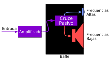
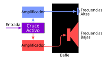
Each speaker should only receive the frequency range intended for it. To do this, the signal can be filtered before amplification (called active filtering) or after amplification (called passive filtering). Passive crossovers do not need power, but they have some disadvantage: They may need large inductances and capacitors due to the power to be supported, since they are after the amplifier. Limited availability of the necessary components that support these powers. They modify the load impedance seen by the amplifier. Unlike active crossovers, which can have gain, passive filters have inherent attenuation in the passband. This usually leads to a reduction in the damping factor of the loudspeaker itself.
Active
An active crossover is an electronic filter that divides the signal into different frequency bands before power amplification, thus requiring at least one amplifier for each band. You can use a passive filter before amplification, but this is not a common technique, as it is less flexible than an active filter. Any solution that uses a crossover before amplification is commonly referred to as a bi-amp, tri-amp and so on depending on the number of channels. They may even include phase or time alignment between the various frequency bands, equalization and dynamic compression.
The design of crossovers quickly becomes quite complex, so more and more, more elaborate filters are done in active format. In fact, the components for the passive filtering are noticeably more critical and the necessary inductances are more expensive as the filtering frequency decreases. For this reason, subwoofers are made almost exclusively with active filtering.
Passive
Traditionally, the vast majority of loudspeakers used passive filtering. This crossover, inserted between the input of the speaker and the speakers, distributes the frequency bands to the corresponding speaker that can reproduce it. It is mainly made up of capacitors, inductors and resistors but can integrate other components to protect the transducers against excess power. Components can be soldered onto a printed circuit board, or even inserted directly into the box's internal wiring for the simplest of implementations. Speakers with integrated passive filter only require the arrival of an amplified sound signal, they do not need power.
A speaker cabinet's passive crossover can be very simple, being limited to a capacitor in series on the tweeter for a two-way speaker. In this case, constituting a 6 dB/octave high-pass filter, the woofer is not filtered and sees its response roll off naturally at the top of its spectrum. sound. This type of filtering is common in the basic range. More sophisticated filters typically have one circuit per way, using multiple components to achieve slopes of 12 dB/octave (second order) or 18 dB/octave (third order). The filter can also integrate correction circuitry for the speaker used.
Contrary to what you might think, passive filtering is not only used in multi-way loudspeakers. In a unidirectional loudspeaker (usually equipped with a single full-range loudspeaker), it is possible to integrate a passive filter intended to improve the frequency response of the loudspeaker used. Naturally, the operation is done at the expense of efficiency, but when this point not critical, this technique can bring a significant improvement in sound quality.
Baffle
Most speaker systems consist of speakers mounted in a baffle or cabinet. The purpose of the baffle is to prevent sound waves coming from the rear of the speakers from destructively interfering with the front. The rear waves are 180° out of phase with the front ones, so without a baffle they create cancellations that degrade both the level and quality of sound at low frequencies.
The simplest baffle is a flat panel with holes where the speakers are mounted. However, in this solution sound frequencies with wavelengths greater than the dimensions of the baffle are canceled due to Acoustic Shorting. With an infinity panel these interferences can be completely eliminated. A sufficiently large sealed box can approximate this performance. Since infinite-dimensional panels are impossible, most loudspeakers work by containing the back radiation of the moving diaphragm. A sealed box prevents back transmission of the speaker by confining the sound in a rigid, airtight box. Techniques to reduce sound transmission through the box walls include: thicker walls, absorbent material, internal supports, curved panels, or more rarely, viscoelastic materials or thin sheets of lead applied to the interior panels.
However, a rigid box reflects sound internally, which is transmitted to the outside through the speaker diaphragm, degrading sound quality. This can be reduced with interior absorption, using absorbent materials (often called "attenuation") such as fiberglass, wool, or synthetic fiber wadding inside the box. The internal shape of the cabinet can also be designed to reduce spin, reflecting sounds away from the diaphragm to where they can be absorbed.
Other types of loudspeakers modify the rear radiation in a way that constructively adds to the signal from the frontal cone. Designs using this principle such as "bass-reflex", "passive radiator" or "transmission line" are often used to extend the effective low-frequency response by increasing the low-frequency response of the loudspeaker.
To make the transition between loudspeakers as seamless as possible, system designers have attempted to time align the loudspeakers by moving their mounting positions forward or backward so that the acoustic center of each loudspeaker is in the same vertical plane. This can also include tilting the front of the speaker back, putting individual cabinets on each speaker, or more rarely using electronic filters for the same purpose. These attempts have resulted in rather unusual loudspeakers.
The way of mounting the loudspeakers, including the cabinets, can cause diffraction resulting in peaks and valleys of the frequency response. The problem is greater at high frequencies, where the wavelengths are similar to or less than the box measurements. The effect can be minimized by rounding the edges of the cabinet, by curving the baffle itself, by using a smaller or narrower cabinet, by relocating the speakers, by using absorbent material around the speaker, or by using a combination of these and other strategies.
Infinite screen
It is a placement system for dynamic speakers, which consists of integrating the speaker into a large flat surface (for example, a wall) with a circular hole in the center (where the speaker cone is housed).
Sealed Box
It is simply an airtight box, the purpose of which is to eliminate acoustic shorting by trapping back radiation in a relatively small volume. It can be filled or padded with absorbent material as needed.
The membrane is in «acoustic suspension», because the volume of air (VB) contained acts like a spring and slows it down. Therefore, its volume must be calculated according to the characteristics of the speaker: resonance frequency at free air (FS or FR), volume of air equivalent to the elasticity of the suspension (VAS) and its total quality factor (QTS).
Bass response retains the best bass extension without over response when QTC = 0.707.
- QTC=QTVASVB+1{displaystyle QTC=QT{sqrt {{frac {VAS}{VB}}+1}}}}}
At comparable volume, the low-end cutoff frequency is higher than in a bass-reflex-type cabinet, but with a smoother slope to 12 dB/octave below the cutoff frequency (Fc).
A very large closed box is called an infinite box. In this case, the air it contains no longer has a spring effect. The result is close to that of the infinite baffle. This type of enclosure can be achieved by integrating one or more speakers on the wall of a room, the infinite box then being the room next door.
Bass reflex box
It is a system for building loudspeakers to improve the response at low frequencies. A port (tube-shaped hole) is opened in one of the walls of the box and all the parameters that affect the internal volume of the box are planned so that the air inside the tube resonates at a certain low frequency.
They are easily identifiable thanks to their port(s). The principle is to recover the back radiation to add it in phase with the front radiation. They are based on the principle of the Helmholtz resonator, consisting of a volume and one (or more) ports. The port is characterized by its surface and its length, which defines a volume of air that circulates in it and therefore a natural frequency, as well as secondary resonances.
Passive radiator
It is a variation of the bass reflex, which uses a woofer without a motor (coil and magnet) instead of the port. The exact term is "passive radiator". It allows for an extension of the bass response, just like its counterpart. This system has better low-frequency response, but is expensive to build and may have some power loss.
Horn Speaker
Horn speakers are the oldest speaker systems. The use of acoustic horns as megaphone voice amplifiers dates back at least to the 18th century and the horns were used in Phonographs mechanical since 1877. A horn loudspeaker uses a shaped waveguide in front of the loudspeaker to increase the directivity of the system. Transforming a small surface with high pressure in the cone to a large surface with low pressure in the mouth of the horn. This transforms the electroacoustic/mechanical impedance between the speaker and the environment, increasing efficiency and focusing sound in one direction.
The size of the throat, mouth, length of the horn, as well as the way it expands, must be carefully selected to suit the loudspeaker and allow this transformation function to occur over a band of frequencies (all speakers perform poorly outside their acoustic limits, both at high and low frequencies). The length and section of the mouth required for low frequencies necessitate horns of more than one meter in length. "Folded horns" may reduce the overall size, but they force the designer to make compromises and further complication of cost and manufacturing.
A horn speaker can have an efficiency of up to 110 dB at 2.83V (1W at 8Ω) at 1 meter. This is one hundred times higher than what is obtained with a dynamic loudspeaker that usually reaches an efficiency of 90 dB and is essential in applications where high sound levels are required or amplification is limited.
Transmission line
It is a speaker cabinet design that uses an acoustic transmission line inside the cabinet. Sound from the back of the speaker is routed down a long, padded (usually folded) duct with a hole at the end that communicates with the outside, creating constructive low-frequency interference with the speaker. Compared to the relatively simple designs of sealed cabinets or bass reflexes, it allows for greater control of energy and resulting sound.
Open baffle (flat baffle and its variants)
It is an open box without a bottom or simply a more or less large plate, which separates the rear wave of the speaker from the front wave, thus limiting the acoustic short circuit. The baffle should be as large as it is desired to go down in frequency. Acoustic shorting still occurs at low frequencies, for wavelengths that exceed the size of the board.
Connection systems
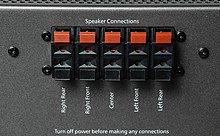
To connect a speaker to an audio signal source, it is equipped with one or more connectors. These connectors differ (at least in principle) depending on whether it is a passive or amplified speaker. In the first case, it is about being able to transmit a power that can be significant (several hundred watts) and a high voltage, potentially dangerous. In the second, the power is negligible and the voltage is low. the requirements are very different. Also, depending on the speaker's intended use (home listening, fixed sound system installation, mobile sound systems, musicians), the connectors and qualities required vary greatly.
Passive speakers
Passive loudspeakers, intended to be connected to a power amplifier, must use connectors capable of transmitting power without appreciable losses and guarantee good safety for both the user and the equipment (without risk of short circuit).
For high-consumption uses (hi-fi and the like) two types of connectors have emerged: on the one hand, pressure terminals (a cable is inserted into a hole by pressing a button and when released, a guillotine system ensures the contact) and terminal blocks will also accept the 4 mm banana plug. These terminal blocks can accept the end of bare or terminal wires. They are often the connectors of choice for demanding hobbyists because they offer a larger contact surface and greater universality of use. Although a European directive prohibits the use of banana plugs for voltages higher than 25V they are still widely used because they are very practical. The main drawback of all these connection modes is the absence of a polarity device. Thus, it is possible to connect a loudspeaker upside down, which does not present any risk, but greatly deteriorates the acoustic reproduction since some of the transducers in the installation have a phase inversion. Therefore, it is necessary to verify this point, the conventional technique consists in using a battery: when a battery is connected to a loudspeaker or an acoustic box, the speaker membrane advances if the connection is correct (positive with positive and negative with negative). and it goes backwards if the connection is in push-pull.
For professional uses, the Speakon connector prevails: specially designed for this use by Neutrik, it does not present a risk of error or inverting the connection and it locks automatically, avoiding any untimely disconnection. There are several models of Speakon connectors to meet specific needs. Professional loudspeakers are almost always equipped with at least two connectors to provide modulation feedback for speaker combinations or other needs.
Musicians have long used (and often still use) 6.35mm jack plugs (1/4 pouce). This connector, very economical and practical, has the drawback of being used for other uses, hence the risk of damage due to confusion. Also (aside from the rather rare angled models) it sticks out from the back of the speaker and can therefore be easily broken. It can also be easily disconnected if the cable is pulled, so its use for this purpose should be avoided. Jacks (at least for this job) are mostly found on semi-pro gear, but may be present in parallel with other connectors, especially Speakon.
Finally, professional XLR connectors have sometimes been used for the connection of passive speakers, but this is not a recommended practice due to the risk of confusion with the usual uses of this type of connector.
Powered speakers
Speakers that incorporate a power amplifier can receive, depending on the model, an analog signal at line level or a digital signal according to a standard corresponding to their use.
Professional loudspeakers (sound system and the like) use, for analog connections, XLR connectors with balanced connections. On mobile equipment, these connectors can be of the "combined" type, allowing the use of an XLR connector and a 1/4" jack connector. Inputs are normally line level, but many models offer a microphone input, sometimes with a mixer. As for the passive speakers, the connectors are doubled to ensure the return of the modulation if necessary.
Speaker characteristics
The main characteristics of a loudspeaker are:
- Power admitted.
- Frequency response.
- Impedance– typically 4 Ω (ohms), 8 Ω, etc.
- Performance and sensitivity– The sound pressure level produced by the speaker in a non-reverberating field, normally expressed in dB and measured at 1 m with an entry of 1 W, normally specified at one or more frequencies.
- Distortion.
- Direct.
- Maximum sound level– The highest sound level that can support the speaker without damaging or exceeding a specified distortion level.
Power
The allowable electrical power rating that the speaker can handle (maximum input power before the speaker is damaged) is not the sound power produced. Higher power is not a guarantee of sound quality either. Damage to the loudspeaker at much less than nominal power can be caused if the mechanical limits of the loudspeaker are exceeded at low frequencies. energies at high frequencies in those cases) or an input with large high-frequency components. In all these situations the tweeter receives more energy than it can handle. The different ways of defining allowable power can be quite confusing. In practice, defining the allowable power of a loudspeaker is difficult. In fact, a loudspeaker is meant to reproduce music in various conditions and not a perfectly defined and stable signal in a laboratory. The best demonstration of these facts is the multiplicity of ways to define (and finally measure) the admissible power of a loudspeaker: nominal power, musical power, program power, peak power, etc. There are standards such as IEC 268-5, AES2-1984 or, older, AFNOR NFC 97-330, but it is difficult to find a consensus.
Understanding and properly interpreting these standards is beyond the reach of the general public. For the latter, the best and most understandable indication is a recommendation, by the manufacturer, of the amplification power to be associated with a loudspeaker: for example "Recommended amplification: 50 to 150 W effective".
The most important definitions are:
- Nominal power Maximum power, on a continuous basis, that can withstand the speaker without deteriorating. If you work on the speaker above this power you will be irremediably damaged as it will not be able to dissipate the heat produced by the electric current that circulates through the coil and it can melt the insulation that covers the copper thread that forms it, causing short circuits or cutting your back by fusion of the copper thread.
- Power RMS It specifies the maximum value of the power with which the speaker can work (on the nominal impedance) without permanent damage (mechanical or thermal), when excited with a signal of continuous senoidal form in a certain frequency band. This measure is commonly known as Quadratic Media Race, abbreviated RMS (English) Root Mid Square) and is the most reliable and commonly extended value to talk about the power of an amplifier.
- Power peak (the signal peak), which can take a limited time the speaker before deteriorating. It corresponds to the maximum instant power value that can be applied for a very short time. This value is very related to another limitation of speakers that is the maximum route of the coil without the destruction of the diaphragm (this problem is called deconado del altavoz). This power is greater than the maximum average power.
Frequency response
The Frequency Response specified as the output over a specified frequency range for a constant input level over the frequency range. Variation margin is sometimes specified as ±2.5 dB For a piece of equipment to be considered of quality, it must cover at least the range of audio frequencies, the frequencies audible to humans, that is, (20-20,000 Hz).
But the frequency response of the speaker is not flat. The ideal loudspeaker should give a uniform response, that is, equal power at all frequencies, but this loudspeaker does not exist. In the technical specifications, the frequency response is usually indicated:
- High fidelity speakers are those who have a variation margin of 6 dB for the audible margin between 20 and 20 000 Hz.
- Outside high-fidel systems, 3 dB variations are also acceptable in a margin of 100 to 15 000 Hz, since in practice the margin of human audibility almost never reaches 20 000 Hz.
Frequency response determines the sound frequencies that will be reproduced by the speaker and how differently from the reference level (usually the level at 1kHz). It can be quickly measured with a spectrum analyzer. The frequency response is often shown in simplified numerical form: typically lower frequency (in Hz) - upper frequency (in Hz or kHz) and accepted error (in decibels). This gives, for example, 40 Hz −18 kHz −6dB. A response without an indication of the accepted error is not helpful, as the error could be considerable.
Stating a frequency response in numerical form, however, provides little information. A response curve, plotted on a Bode plot, is preferable. However, (for a loudspeaker system) it is a complex document that needs to be interpreted by competent people to obtain relevant information. In addition, a correct interpretation requires knowing under what conditions and with what technical parameters it was recorded. Typically, the abscissa on the graph represents frequency and runs from 20 Hz to 20,000 Hz and the ordinate represents the level in dB.
In practice, it is necessary to distinguish the response curves intended for the home user, which are simplified versions and give a general idea of the response of a loudspeaker, and the curves intended for engineers and technicians, which are much more detailed, but also more complex. Ultimately, simplified curves become something of an illustration or even a publicity document: this type of document was very popular in the hi-fi boom years. However, there are relatively simple response curves to understand and interpret: the one-third octave curves. They attempt to match the actual hearing capabilities of the human ear.
Recording and plotting the response curve of a loudspeaker has long been a complex operation, often lengthy and requiring expensive equipment and if possible an anechoic chamber. The availability of powerful and inexpensive computers and digital signal processing have made a significant difference, measurements often use a computer associated with an interface and specialized software (some are free). This system makes it possible to perform (under certain conditions and within certain limits) measurements comparable to those obtained in an anechoic chamber very quickly.
Impedance
Impedance is an essential characteristic of a loudspeaker. It is expressed in ohms. It must be known (at least approximately) for a good adaptation to the amplifier used. To do this, manufacturers specify a standard or nominal impedance for their loudspeakers. The most common values are 4 and 8 Ω but other values are possible. In principle, the specifications of the amplifier used indicate what impedance values are acceptable. This is the load impedance. It is not, in any case, an impedance match but rather indicates a compatibility between equipment.
The load that a speaker presents to the amplifier consists of a complex impedance, a combination of resistance and reactance (capacitance and inductance) we have that the voice coil is inductive, the transducer has mechanical resonances, the box modifies the mechanical characteristics and therefore electrical and the passive crossover contributes its own modifications. Most amplifier specifications are given assuming an ideal resistive load, however a loudspeaker, as we have seen, does not have a constant impedance across its frequency band, not only in modulus but also in phase. Some amps can handle these modifications better than others. To study a loudspeaker, we write down its impedance curve, the variation of impedance as a function of frequency. This curve allows obtaining certain technical information, to verify that certain construction errors have been avoided, but also to determine the value that must be indicated for the nominal impedance.
Efficiency and performance
The performance of a loudspeaker expresses the relationship between the acoustic power radiated and the electrical power consumed. Performance is expressed in % and is calculated as follows: Performance = Radiated acoustic power/Delivered electrical power . In fact, performance is rarely measured or used because it is of little practical use. Loudspeaker performance is generally very low, between 0.3 and 3%, the rest being converted to heat. The main cause of low performance is the difficulty of matching the acoustic impedance between the transducer and the air it radiates onto. It should be noted that this performance is variable depending on the frequency of measurement, which complicates its assessment, without taking into account other more complex parameters. Therefore, its usefulness and appreciation are not the domain of the home user.
Electroacoustic efficiency (also called sensitivity) measures the relationship between the electrical input level to the loudspeaker and the sound pressure obtained. Indicated as: sound pressure (in dBspl) obtained at 1 m when a voltage of 2.83 is applied V at speaker input (2.83 V with a nominal impedance of 8 Ω i.e. a power of 1 W: P = U2/R = 2.832/8 = 1 W) Usually given as: dB/2.83 V/1 m because audio amplifiers are similar to a generator voltage and it is possible to ignore the impedance and therefore the power actually absorbed Here again the measurement is a complex operation the result can be influenced by many parameters such as the signal used for the measurement Generally pink noise is used (AES 1984) with 6 dB peak for measurements.
Although the previous expression is technically the most correct, efficiency is usually expressed in dB/1 W /1 m: acoustic pressure in dBspl, for an absorbed power of 1 W with the free field pressure being measured at a distance of 1 m In practice, the power actually absorbed is rarely measured and this expression is misleading.
Knowing the efficiency, the speaker impedance and the applied voltage, it is possible to calculate the sound pressure level at 1 m: Pressure in dBspl= sensitivity + (10logU2/Z), U the voltage and Z the impedance. For other distances it is necessary to subtract 20*log(distance in meters). This only applies to spherical radiation in free field, i.e. 4 pi steradians and corresponds to 6 dB of attenuation each time the distance is doubled. Therefore, these are theoretical values, most of the time quite far from the practical values that depend on reflections in the environment.
For example, if we apply a signal with an amplitude of 32 volts rms to a speaker that has an efficiency of 90 dB / 1 W / 1 m and an impedance nominal of 8 Ω the pressure at 1 m will be 90 + 10*log (322/8) = 111 dBspl A 7 m and the pressure will be 111 - 20*log 7 = 94.1 dBspl. Let us insist on the fact that this is a theoretical calculation, the free field conditions are never fulfilled in the real world.
- Efficiency of household speakers is usually oscillating between 85 dB and 95 dB- a yield of 0.5–4%.
- Efficiency of megaphone speakers or concerts usually ranges between 95 dB and 110 dB- a yield of 4-20%.
In the speaker, unlike the microphone, the sensitivity is not an indication of "sound quality", since practice has shown that lower-sensitivity speakers produce better "sound coloration".
It is generally not possible to combine high efficiencies with compact cabinets and adequate low frequency responses. For the most part we can only optimize two of the three parameters when designing a loudspeaker. If we are looking for extended bass frequency and compact size, we have to accept low efficiency. This rule of thumb is called "Hofmann's Iron Law" (named after J. Anton Hofmann, the H of KLH company).
Distortion
The loudspeaker is one of the most distorting audio systems, so manufacturers often don't provide consumers with distortion figures for their loudspeakers. The distortion has very varied causes: air gap flow, partial vibrations, frequency modulation on the diaphragm, non-linearity of the suspensions, etc.
- Most of the distortion is concentrated in the second and third harmonic, so it will affect to a greater extent the serious tones. This is a distortion around 10%.
- In the mean and high frequencies this distortion is proportionally much lower and does not reach 1 %, although in the high frequency horns this distortion reaches up to a margin of between 10 and 15 %.
Directivity
It is easy to see, moving relative to the diffusion axis of a speaker, that the sound changes as one moves away from this axis. If we measure the frequency response off axis we will see that it differs from the result obtained on axis. This difference is more or less important depending on the speaker design. It generally results in a gradual decrease in treble level (because directivity increases with increasing frequency), but other configurations are possible. This phenomenon means that the listener only really meets expectations from a given angle to the axis. for this reason, it is preferable for the listener to sit directly in front of the speakers. {AP|Directivity} Directivity is rarely specified for consumer speakers, but it is an essential specification for professional models. The manufacturer indicates the angle at which the speaker can be used and at what level of attenuation. This is only the horizontal directivity, but a similar phenomenon occurs on the vertical axis. Therefore, directivity is indicated from both angles. For example 60° × 40°: sixty degrees horizontally and forty degrees vertically, for a fade of 6 dB with respect to the on-axis response.
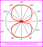
The most graphic way to give the directivity is by means of a polar diagram, which is normally included in the specifications, since each model has a specific response.
A polar diagram is a technical drawing that reflects the speaker's radiation in space, in degrees, for each point on its axes (horizontal and vertical).
Depending on its directivity it can be said that the radiation from a loudspeaker is:
- Omnidirectional. — They radiate the same in all directions, that is, in the 360°.
- Bidirectional. — The polar diagram is eight, it is symmetrical.
- Cardioid. — It is so called because its polar diagram is heart-shaped (cardioid curve), which translates into radiating towards the front and has a minimum sensitivity on its back.
Maximum sound level
The Maximum Sound Level at 1 meter, sometimes called for misuse of language «maximum SPL», It is almost never indicated for consumer speakers, but it is an important element for professional speakers, for cinema or home cinema. It allows the user to assess and possibly calculate if they will have a sound level that meets their needs. The theoretical maximum level that can be obtained can be calculated from the efficiency and the admissible power, however, other factors intervene in the level actually obtained, for example, directivity and thermal compression. Therefore, the calculated value is not exact in practice. The indication of the maximum level is therefore a kind of compromise on the part of the manufacturer that allows the user to quickly assess the possibilities offered in this area.
Typology
Number of ways
To properly reproduce the entire audible spectrum, a single speaker is insufficient. Therefore, we are forced to use several speakers in the same speaker, each one specialized in a part of the audible spectrum: bass, midrange, treble. Each band of the spectrum is called a way, and the splitting is done by a crossover: this usually results in either two-way (minimum of two speakers) or three-way (minimum of three speakers) speakers.. There may be a larger number of pathways (four or more) but these complex formulas are not common.
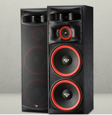
Note that the number of speakers and the number of channels are not necessarily identical. For example, a loudspeaker can use several speakers (usually identical) for the reproduction of the same channel (see image on the side). This technique is often used for bass reproduction to allow, for example, the use of small diameter speakers without making the sound level too low.
The last type of filtering is “Half Way”, the most common configuration is two and a half ways. The principle is to use two identical loudspeakers for the low channel of the spectrum, one of the two loudspeakers being low-pass filtered with a cut-off frequency before the other. The objective is to improve the level in the bass avoiding interference between two transducers in the midrange.
Speaker Format
Satellite speaker
Panel loudspeaker or distributed mode loudspeaker: Its electrical, mechanical and acoustic properties differ drastically from conventional loudspeakers as it uses the principle of optimum distribution of the vibration modes of a thin rigid plate that have been excited by a small transducer at one point on the panel. In this way, it is possible to radiate a wide range of frequencies in all directions with a considerable level of pressure and very low distortion.
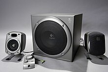
The term "satellite" refers to generally small-sized speakers designed to be used in conjunction with a subwoofer. The term comes from the comparison with a satellite that revolves around the star on which it depends. The satellites generally reproduce mid to high tones and the subwoofer, the low tones. This system is widely used in sound systems, home theaters and multimedia speakers for computers. For example, we are talking about a 2.1 acoustic system (two satellite speakers and a subwoofer) or even a 5.1 (five satellites and a subwoofer).
The speaker system configuration should not be confused with the number of audio channels of the source (DTS 5.1, Dolby Digital 5.1) which have nothing to do with it. A 2.1 system is generally used to play a stereo (two channel) source, whereas in a home theater context, 5.1 or 7.1 systems take multi-channel signals (Dolby Digital, DTS, etc.) into account.
In 5.1 or 7.1 configurations, used in home theater, the satellites are placed around the listener so that they can discern sounds coming from the front (dialogue, for example), sounds coming from the sides or rear. This contributes to the immersion in the film.
Bookshelf speaker
The bookshelf speaker (in English: bookshelf), or "compact speaker", It is a small-sized model, originally intended, as its name suggests, to be placed on the shelves of a library. This type of speaker is especially suitable for those who don't have a lot of space to give them. They can also be placed on suitable feet to place them at the height of the ears, without the need to place them on a piece of furniture. These speakers are usually two-way, with a tweeter and a woofer. They also usually include a bass-reflex port, placed on the front or rear to save space on the front panel.
Compared to loudspeakers, they are often more limited in bass extension and volume, and are better suited for smaller sound rooms. They can be used in stereo, but can also be used in the rear as surround sound in a home theater setup.
Column speaker
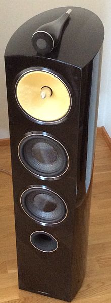
As the name suggests, a floorstanding speaker is a model that is much taller than it is wide and is intended to be placed directly on the floor. Indeed, a conventional speaker must be placed on a support (special support, furniture, etc.) so that the sound emission from the subwoofer is not disturbed by the proximity of the ground and that the midrange and treble speakers are located approximately at the ear level of the listeners. In such a configuration, the volume between the box and the floor is often 'wasted'. The idea of the column speaker is to use this volume to increase the volume of the speaker without increasing its size. These are generally the models that offer the best ratio between extension and magnitude of bass restoration and volume, since any occupied volume is used as acoustic load. There is also no need to worry about finding a suitable support.
Commonly used in hi-fi, they are also often used in home theater as left and right speakers, accompanied by a center speaker and sometimes a subwoofer.
Wireless speaker
They are very similar to traditional wired speakers, but they receive the audio signal using radio waves (usually using the Bluetooth standard) instead of audio cables. they always include a built-in amplifier as radio waves do not provide enough power to drive the speaker. This integration of amplifier and speaker is known as an active speaker. The manufacturers of these types of speakers usually design them in such a way that they are as light as possible while delivering the highest possible sound power in the most efficient way. Wireless speakers also need power to power them, so they require batteries or alternatively plug into an AC outlet, in which case only the cable to the amplifier is eliminated.
Types of speakers (transducers)
There are many more types, but these are the most common and used.
With Diaphragm
Dynamic speaker or moving coil speaker
The input electrical signal acts on the voice coil that creates a magnetic field that varies according to said signal. This magnetic flux interacts with a second continuous magnetic flux normally generated by a permanent magnet that is part of the body of the loudspeaker, producing a magnetic attraction or repulsion that moves the mobile coil, and with it the diaphragm attached to it. When the diaphragm vibrates, it moves the air that is located in front of it, thus generating pressure variations in it or vibrations, or what is the same, sound waves.
Its commercialization began in 1925. Since then, and after more than 9 decades, it continues to be the most widely used. In addition to being the most common speaker, it is also cheap (probably, it may be a cause-and-effect relationship)
Moving Iron Speaker
This design is the original of the first speaker, going back to the first phones. It uses a static coil that vibrates a magnetized piece of metal (called iron or armor). The iron is attached to the diaphragm, or is the diaphragm itself. Moving iron loudspeakers are inefficient and reproduce a limited band of frequencies. They need large magnets and coils to increase force, compared to moving coil.
A variation called the balanced armature uses an armature that moves like a seesaw. Since they are not damped they are highly efficient, but they also produce strong resonances. They are still used today for headphones and earphones, where a small size and high efficiency are important.
Piezoelectric speaker
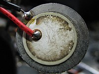
In these loudspeakers, the motor is a piezoelectric material, which upon receiving a voltage difference between its metallized surfaces experiences elongation and compression. If a diaphragm is attached to one of its faces, it will undergo displacements capable of producing a radiated pressure at an audible frequency. It is not very linear, with low performance and its use is limited to high frequencies.
Piezoelectric speakers are often used as buzzers in watches and other electronic devices and are sometimes used as a tweeter in inexpensive systems such as computers and portable radios. Piezoelectric loudspeakers have several advantages over conventional loudspeakers: they resist overloads that would destroy other high-frequency loudspeakers, they can be used without a crossover due to their electrical properties. They also have drawbacks, some amplifiers can oscillate with a capacitive load like a piezo speaker, causing distortion and/or damage to the amplifier. In addition, its frequency response is in most cases lower than that of other technologies. Therefore its use is limited to non-critical applications or as a buzzer (single frequency). Piezoelectric loudspeakers have an extended response to high frequencies, this is very useful in specific applications such as sonar where piezoelectric variants are used both as output devices (to generate sound underwater) and as input devices (acting on such as underwater microphone sensors). In addition, they have other advantages in these applications, their simple and robust construction resists seawater better than a tape or membrane. In 2013 Kyocera introduced an ultra-thin piezo speaker with a depth of just 1mm for its 55" OLED TVs, providing better clarity than a conventional TV speaker.
Magnostatic speaker
Instead of a coil moving a diaphragm, a magnetostatic speaker uses an arrangement of metal strips attached to a large, thin, flat membrane. The current signal passing through the strips interacts with the magnetic field of the permanent magnets mounted behind. The force produced moves the membrane and therefore the air in front of it. Generally these designs have lower efficiency than dynamic loudspeakers.
Elastic magnet speaker
They are based on the property of magnetostriction, they have been used mainly in sonar applications, ultrasonic sound radiators, but their use has also been extended to audio systems. Magneto-elastic loudspeakers have specific advantageous properties: They can provide a large force with a small excursion than other technologies, small excursions prevent distortion, the magnetizing coil remains static and therefore easier to cool, they are robust as they do not require delicate suspensions. Fostex produces magnetoelastic transducers and FeONIC have also made transducers for subwoofers.
Electrostatic speaker
These loudspeakers have a condenser structure, with a fixed plate and a mobile one (the diaphragm), between which the electrical energy supplied by a direct voltage source is stored. When the energy stored between the plates is increased, an electrical attraction or repulsion force is produced between them, causing the movable plate to move, creating useful pressure. They cost more than dynamic ones.
They use a high-voltage electric field (instead of a magnetic field) to drive a thin, electrostatically charged membrane. Being driven by the full surface of the diaphragm, rather than a small voice coil, they typically provide a more linear motion with less distortion than dynamic loudspeakers. They have a relatively narrow scattergram, which creates precise positioning of the sound field. However, the optimal listening area is small and they are not very efficient. The biggest drawback is that due to practical construction limitations, the excursion of the membrane is limited. The further apart the grids are from the stators, the higher the working voltage must be to have an acceptable efficiency, this increases the tendency to produce electric arcs and the attraction of dust. Arc flash is a potential problem with current technologies, especially when dust is deposited or used with high level signals. Electrostatic loudspeakers are inherently dipole radiators and due to their thin, flexible membrane, are not suitable for using baffles that reduce low-frequency cancellation. Because of this and their limited excursion, full-range electrostatic loudspeakers are naturally large, with the cut-off frequency being one quarter of the wavelength of the smallest dimension of the panel. To reduce the size of commercial products, an electrostatic at high frequencies is sometimes used combined with a conventional dynamic speaker that handles low frequencies efficiently. Normally, electrostatic speakers are powered through a step-up transformer, which multiplies the voltage produced by the amplifier. This transformer also multiplies the capacitive charge inherent in electrostatic loudspeakers, which causes the effective impedance presented to the amplifier to vary significantly in frequency. A loudspeaker rated at eight ohms has a one ohm load at high frequency, which can be problematic for some amplifiers.
Ribbon and planar magnetic speaker
It consists of a thin metallic film suspended in a magnetic field. When an electric current is applied to it, it moves and produces sound. The advantage is that the tape has very little mass, so it can accelerate quickly, obtaining very good response at high frequencies. They are usually quite fragile, a strong gust of air could break them. They emit sound with a dipole diagram, although sometimes they have baffles that limit back radiation. Ribbon designs need very strong magnets, making them expensive to manufacture. They have a very low resistance that many amplifiers cannot drive directly, so a step-down transformer is used to increase the current flowing through the tape. The transformer must be carefully designed so that its frequency response and parasitic losses do not degrade the sound, increasing costs and complication compared to conventional designs.
The planar magnetic speaker has the coil printed on a flat diaphragm, the current that runs through it interacts with the magnetic field created by magnets carefully placed on either side of the membrane, causing it to vibrate more or less evenly without bending or wrinkling. By spreading the force over a large part of the surface, the resonance problems inherent in flat-diaphragm moving coil loudspeakers are reduced.
AMT loudspeaker (Air Motion Transformer)
Oskar Heil invented the AMT loudspeaker in the 1960s. A folded diaphragm is mounted in a magnetic field and opens and closes according to the sound signal. The air comes out from between the sheets following the signal, generating sound. These loudspeakers are less fragile than ribbon loudspeakers and considerably more efficient (we get a higher sound power level) than ribbon, electrostatic, or planar magnetic designs. ESS, a Californian manufacturer, licensed the design and contracted to Heil, producing a range of loudspeakers using their tweeters in the 1970s and 1980s.
Bending Wave Speaker
Bending wave loudspeakers use an intentionally flexible diaphragm. The rigidity of the material increases from the center to the outside. Waves of short length radiate mainly from the inside, while waves of longer length reach the outer edge of the membrane. To avoid reflections back to the center the waves are absorbed by a damper at the outer edge. These loudspeakers can cover a very wide band of frequency (80 Hz - 35,000 Hz) and have been promoted as a good approximation of a point sound source. This unconventional solution is used by very few manufacturers, in various configurations.
Ohm Walsh loudspeakers use a unique transducer designed by Lincoln Walsh who had been a radar development engineer during World War II. He became interested in audio equipment design and his latest project was a single-way single-drive loudspeaker system. The cone (membrane) faces down into a closed box. Instead of moving in and out, as conventional transducers do, it rippled creating sound similar to a radio frequency transmission line, creating a cylindrical sound field. Walsh died before commercially releasing his speakers. The brand Ohm Acoustics has produced several loudspeaker models with this design since then. The German brand German Physiks also produces speakers with this approach. The German brand Manger has designed and produced a bending wave loudspeaker, which at first seems conventional. In fact, the round membrane attached to the voice coil folds in a controlled manner for full-range sound. Josef W. Manger was awarded the Diesel Medal for outstanding developments and inventions by the institute german inventions
Transparent ion conduction speaker
In 2013, a research team presented a transparent ionic conduction speaker where two layers of transparent conductive gel with a transparent rubber layer between them, using high voltages, allows to reproduce sounds with good quality. It has applications in robotics and laptop computers.
No Diaphragm
Plasma Arc Speaker
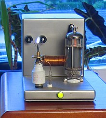
Plasma speakers use plasma as the radiant element. Because plasma has very little mass and is electrically charged, it can be manipulated with an electric field, resulting in a linear response up to frequencies well above the audible range. Reliability and maintenance issues make it unsuitable for use in consumer products. In 1978 Alan E. Hill of the US Air Force Weapons Laboratory in Albuquerque (NM) designed the ''Plasmatronics Hill type I'' a tweeter with a helium plasma generator, this avoided ozone and nitrous oxide generated by radio frequency air decay from earlier models of plasma tweeters, such as the Dukane Corporation's Ionovac pioneered during the 1950s. This design is currently used by some German manufacturers. A cheaper variation of this principle is to use a flame as a transducer, since flames contain ionized (electrically charged) gases.
Thermoacoustic speaker
In 2008, researchers from Tsinghua University presented a carbon nanotube thin-film thermoacoustic speaker, the operating mechanism of which is a thermoacoustic effect. Electrical currents at audio frequencies are used to heat the nanotubes, resulting in the generation of sound in the surrounding air. This speaker is transparent, elastic and flexible. In 2013, researchers from Tsinghua University expanded the project with a headset featuring a carbon nanotube string speaker in a surface-mounted thermoacoustic device, they are embedded devices compatible with silicon semiconductor technology.
Rotary woofer
A rotary woofer is basically a fan with variable pitch blades. The pitch is controlled by the audio signal, allowing you to modulate the amount of air displaced and create sound pressure waves. They allow efficient reproduction of infrasound frequencies that are difficult or impossible to reproduce with a conventional diaphragm loudspeaker. They are used in movie theaters to create deep sound effects such as explosions.
Listening environment
The interaction between a loudspeaker system and its environment is complex and fundamentally outside the control of the loudspeaker designer. Most listening rooms present a reflective environment, depending on the size, shape, volume, and furnishings. This means that the sound reaching the listener is not only the direct sound from the speaker, but also the same sound delayed and modified by reflections from one or more surfaces. These reflected sound waves added to the direct sound cause cancellations and additions at different frequencies (for example, by the resonance modes of the room) changing the timbre and envelope of the sound reaching the listener. The human brain is very sensitive to small variations in these parameters, which is partly why a speaker system does not sound the same in different positions or rooms. A significant factor in the sound of a speaker system is the amount of absorption and diffusion present in the environment. Clapping your hands in an empty room with no carpets or curtains produces a shimmering, shimmering sound, due to lack of absorption and reverberations (repeated echoes) from flat, reflective surfaces, walls, floors, and ceilings. Adding furniture, paintings, shelves and even baroque plaster ceilings changes the echo, mainly by diffusion caused by reflective objects with sizes of the same order of magnitude as sound waves. This breaks up single reflections off flat bare surfaces and spreads the incident energy over a larger angle of reflection.
Location
In the typical rectangular listening room, the parallel reflective surfaces of the walls, floor and ceiling cause primary acoustic resonance nodes in each of the three dimensions. In addition there are more complex resonance modes involving three, four, five and even all six boundary surfaces to create standing waves. Low frequencies excite these modes more as they are not affected by the composition or placement of the furniture. Mode separation is critical, especially in small to medium-sized rooms like recording studios, home theaters, and broadcast studios. The proximity of the loudspeakers to the boundaries of the room affects the intensity with which the resonance modes of the room are excited and their relative intensity at each frequency. The listener's location is critical, as a position close to a boundary can have a large effect on the perceived frequency balance. This is because standing wave effects are greatest in these locations and at low frequencies, below the Schroeder frequency: typically around 200–300 Hz, depending on the size of the room.
Home theater
The so-called 'Home Theater' o Home cinema is a system or set of several speakers that tries to bring the sound quality closer to that heard in a movie theater. They can be observed:
- version 5.1, which requires six speakers:
- Speakers on the left, center and right all on the front.
- Later left and right with enveloping effect.
- A subwoofer (which is considered as a "1" channel due to the narrow frequency band it reproduces). This speaker can reproduce the low frequencies of all channels or can only do so for those speakers who do not achieve it. This is usually managed by the configuration of an amplifier in 'long' or 'cut' mode defining the type of speaker.
- version 6.1 similar to 5.1 but with the addition of a central channel in the back of the room.
- version 7.1 identical to 5.1 only with speakers left and right in the central part of the room. For the SDDS system, 7.1 is equal to 5.1 but adding additional right and left central speakers to the listener's front to improve the sound setting.
- version 7.2 identical to 7.1 but with the addition of another subwoofer, usually at the back of the room.
It is important to note that the sound channels delivered to the speakers could be original individual channels (usually in 5.1) or could decode additional channels for surround channels (This distribution must be accompanied by a Dolby Digital EX decoder and a THX decoder Surround) or be simulated (where the two surround channels are expanded to either the center rear or the twin rear speakers, as the case may be).


