Simple machine
A simple machine is a mechanical device that changes the direction or magnitude of a force.
From the dawn of the Industrial Revolution to the present, the theoretical conception of machines has evolved considerably. However, the classic concept of simple machine continues to be valid, both for its historical significance and for being a valuable didactic element widely used in the teaching of some basic notions. of physics. On the other hand, numerous simple mechanisms based on simple machines are still generally used for artisan production.
The classic simple machines
According to the traditional classification, the six simple machines are:
| The six classic simple machines: | ||||||
|---|---|---|---|---|---|---|
|
Lever
| Types of lever: | ||
 |  |  |
| 1.a Class | 2nd Class | 3rd Class |
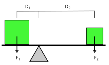
- The lever is a rigid bar with a support point, called fulcro, to which a force is applied and which, turning on the support point, overcomes a resistance. The conservation of the energy is fulfilled and, therefore, the force applied by its travel space must be equal to the strength of resistance through its travel space.
Lathe
- It is a mechanical device usually used to move vertically large weights. It is formed by a rope from which one of the ends is fixed to the load to move and the other end to a cylinder that is in turn fixed so that it can only rotate around its main axis. Acting the cylinder with a crank the rope rolls over on it, getting the load up.
Pulley
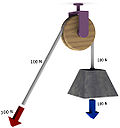
- It is a mechanical traction apparatus made up of a corrugated or rolled wheel where a rope passes, which allows to transmit a force in a different direction than applied. In addition, forming pairs or polypastes of two or more pulleys it is also possible to increase the magnitude of the force transmitted to move heavy objects, in exchange for the reduction of the displacement produced.
Inclined plane
- In the tilted plane a force is applied to overcome the vertical resistance of the weight of the object to lift. Given the principle of energy conservation, the smaller the angle of the tilted plane, the more weight can be raised with the same applied force, but in return, the distance to go will be greater.
Wedge
- The wedge transforms a force applied to its blunt end into two forces perpendicular to the first and the opposite sense between them. The wedge angle determines the proportion between the applied force and the resulting force, in a manner similar to the tilted plane. It's the case of axes or knives.
Screw
- The mechanism transforms a rotary movement applied to a steering wheel or handle, into another rectilinear in the spindle, using a screw and nuts mechanism. The force applied by the length of the wheel circumference must be equal to the resulting force by the spindle advance. Given the great development of the circumference and the normally small advance of the spindle, the relationship between the forces is very large. Tools like the cat of the car or the corkscrew derive from the operation of the screw.
Despite the traditional character of the previous list, it is not uncommon to find other lists that include a different mechanical element. For example, some authors consider the wedge and the screw as applications of the inclined plane; others include the wheel as a simple machine; others consider the gears; or the axis with wheels is also considered a simple machine, even if it is the result of joining two other simple machines.
Features
A simple machine uses a single applied force, transforming it into a resultant force, which does work by displacing a single load (or overcoming a resistant force). Neglecting friction losses, the work done by the applied force is equal to the work done by the resultant force on the load. The machine can increase the magnitude of the applied force over a given distance (by transforming it into the resultant force), but at the cost of a proportional decrease in distance traversed by the load. The relationship between the applied force and the resultant force is called mechanical advantage.
Simple machines can be thought of as the "building blocks" elements from which more complex machines are designed (sometimes called "compound machines" as for example, the mechanism of a bicycle, where wheels, levers and pulleys are used). The mechanical advantage of a compound machine is the product of the mechanical advantages of the simple machines of which it is composed.
History
The idea of the simple machine originated around the III century BCE. C. with the Greek physicist Archimedes, who studied the lever, the pulley, and the screw. He discovered the principle of mechanical advantage, reflected in the famous phrase traditionally attributed to Archimedes regarding the lever: "Give me a foothold, and I will move the Earth." (in Greek: "Δώσε μου ένα σημείο τη Γη.", και θα μετακινήσω τη Γη.") the amount of force amplification that could be achieved through the use of mechanical advantage, a concept he extended to the pulley and screw, describing their manufacture and uses. However, the Greeks' understanding was limited to the statics of simple machines (the balance of forces); and it did not include consideration of dynamic effects, the balance between force and distance, or the concept of mechanical work.
During the Renaissance the dynamics of mechanical powers, as simple machines were called, began to be studied from the point of view of how far a load could be lifted, or of the force that could be applied. This eventually led to the new concept of mechanical work. In 1586, the Flemish engineer Simon Stevin deduced the mechanical advantage of the inclined plane, which led to its inclusion with the other simple machines. The complete dynamical theory of simple machines was elaborated by the Italian scientist Galileo Galilei in 1600 in his work Le Meccaniche (On Mechanics), in which he showed the mathematical similarity underlying the different machines. He was the first to understand that simple machines do not create energy, but only transform it.
The classical rules of sliding friction in machines were discovered by Leonardo da Vinci (1452-1519), but he did not include them in his notebooks. They were rediscovered by Guillaume Amontons (1699) and developed by Charles-Augustin de Coulomb (1785).
Modern mechanics has expanded the notion of simple machines, which described too succinctly the wide variety of complex machines that arose from the Industrial Revolution. Since the 19th century, authors have compiled extended lists of "simple machines", often using terms as basic machines, compound machines, or elements of a machine, to distinguish them from simple machines earlier classics. By the late 1800s, Franz Reuleaux had identified hundreds of elementary mechanisms, which he called simple machines. Representations of the (KMODDL) design of these devices can be found on the kinematic models on the Cornell University website.
(See: Link to Cornell Mechanism Catalog)
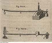
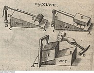
| Simple machines (Johann Sturm, 1676) | |||||
Since 1970, with the progressive generalization of digital technologies, numerous computer-aided design tools have been developed (Autodesk Inventor, SolidWorks, Pro/ENGINEER, CATIA and Solid Edge are among the most widely used) including in its routines the modeling of various mechanisms, allowing a virtual visualization of the kinematic behavior of the designed devices.
Mechanical analysis
Although each type of simple machine works in a different way from a mechanical point of view, from an analytical point of view they are all governed by the same mathematical equations. This being true, from a theoretical point of view their operation can be analyzed in two different ways: without considering friction (ideal machines) and considering it (real machines).
The operation of compound machines is also analyzed, as assemblies of series of simple machines.
Ideal Machines
When the effect of friction losses on the operation of a simple machine is not considered, then one is talking about ideal machines.
A force Fa{displaystyle F_{text{a}},} applies to the device at a given time, and performs a job when moving a load Fr{displaystyle F_{text{r}},} At another point. Although some machines only change the direction of the force, as it does a simple pulley, most machines multiply the magnitude of the force by a factor, the mechanical advantage
- VM=Fr/Fa{displaystyle mathrm {VM} =F_{text{r}}}/F_{text{a}}}{,}
which can be calculated from the geometry (and if applicable, from the friction) of the machine.
Simple machines do not own a source of energy (unlike motors), so they cannot perform more mechanical work than they receive by applied force. A simple machine in which the effects of friction and the elasticity of materials can be despised is called a ideal machine. Due to the principle of energy conservation, in an ideal simple machine, the power produced (power production rate) Pr{displaystyle P_{text{r}},} equals the applied power Pa{displaystyle P_{text{a}},} at any time:
- Pr=Pa{displaystyle P_{text{r}}=P_{text{a}}}{!}
The output power is equal to the load speed vr{displaystyle v_{text{r}},} multiplied by heavy load strength Pr=Frvr{displaystyle P_{text{r}}=F_{text{r}}v_{text{r}}}{text{r}}}!. Similarly, the input power is equal to the speed of the applied force va{displaystyle v_{text{a}},} multiplied by the value of the applied force itself Pa=Fava{displaystyle P_{text{a}}=F_{text{a}}}v_{text{a}}}{text{a}}}. So,
- Frvr=Fava{displaystyle F_{text{r}}v_{text{r}}=F_{text{a}}}v_{text{a}}{,}
Consequently, the mechanical advantage of an ideal machine is equal to the speed ratio between the speed of the applied force and the speed with which the load moves:
VMideal=FrFa=vavr{displaystyle mathrm {VM} _{text{ideal}}={F_{text{r}}} over F_{text{a}}}}={v_{text{a}}} over v_{text{r}}}{,}
The speed ratio of the machine is also equal to the ratio between the distances traveled by the points of the load and the points of the applied force:
- vrva=drda{displaystyle {v_{text{r}} over v_{text{a}}}}={d_{text{r}} over d_{text{a}}}{,}
and can be calculated from the geometry of the machine. For example, the speed ratio of the stick is equal to the ratio between the lengths of its arms.
The mechanical advantage can be greater or less than one:
- Yeah. 1,}" xmlns="http://www.w3.org/1998/Math/MathML">VM▪1{displaystyle mathrm {VM} 한1,}
1,}" aria-hidden="true" class="mwe-math-fallback-image-inline" src="https://wikimedia.org/api/rest_v1/media/math/render/svg/ce3bc7ef66ef073da87e15ef52aed653275d5a6a" style="vertical-align: -0.338ex; width:8.522ex; height:2.176ex;"/> the resulting force is greater than the applied, and then the machine acts as a force amplifier, but the distance traveled by the load dr{displaystyle d_{text{r},} is less than the distance traveled by the applied force da{displaystyle d_{text{a}},}.
- Yeah. <math alttext="{displaystyle mathrm {VM} VM.1{displaystyle mathrm {VM} lice1,}<img alt="{displaystyle mathrm {VM} the resulting force is less than the applied force, but the distance to which the load moves dr{displaystyle d_{text{r},} is greater than the distance traveled by the applied force da{displaystyle d_{text{a}},}.
In a screw, in which a rotational movement is used, the applied force must be replaced by the torque, and its speed by the angular velocity with which the screw is turned.
Real machines. Efficiency
All real machines have friction, which makes part of the applied power dissipate in the form of heat. Yeah. Pf{displaystyle P_{text{f}},} is the power lost by friction, from the principle of energy conservation it is deduced that
- Pa=Pr+Pf{displaystyle P_{text{a}}=P_{text{r}}+P_{text{f}}{,}
Efficiency MIL MIL {displaystyle eta ,} of a machine is a number between 0 and 1 that is defined as the relationship between the applied power and the resulting power, being a measure of the energy losses
- MIL MIL ≡ ≡ PrPa{displaystyle eta equiv {P_{text{r}} over P_{text{a}}}}{,}
- Pr=MIL MIL Pa{displaystyle P_{text{r}}=eta P_{text{a}}{,}
As before, power is equal to force times velocity, and so
- Frvr=MIL MIL Fava{displaystyle F_{text{r}}v_{text{r}}}=eta F_{text{a}v_{text{a}},}
Therefore,
VM=FrFa=MIL MIL vavr{displaystyle mathrm {VM} ={F_{text{r}} over F_{text{a}}}}}{v_{text{a} over v_{text{r}}}}}{,}
Thus, in non-ideal machines, the mechanical advantage is always equal to or less than the speed ratio multiplied by the efficiency η, so that a machine in whichever friction is considered, will not be able to move as large a load as the corresponding ideal machine using the same drive force.
Compound machines
Compound machines are a mechanical device formed from a set of simple machines connected in series, so that the force resulting from one provides the force applied to the next. For example, a vice consists of a lever (the handle of the vise) connected in series with a vise, and a speed reducer consists of a set of shafts and gears (operating mechanically as if they were lathes) connected in series. series.
The mechanical advantage of a compound machine is the ratio of the resultant force exerted by the last machine in the series, divided by the force applied to the first machine, which is
- VMcomposite=FrNFa1{displaystyle mathrm {VM} _{text{composed}}}={F_{text{rN}}} over F_{text{a1}}}}{,}
Because the resulting strength of each machine is applied in the following, Fr1=Fa2,Fr2=Fa3,...... FrK=FaK+1{displaystyle F_{text{r1}}=F_{text{a2}}},;F_{text{r2}}}=F_{text{a3}},ldots ;F_{text{rK}}=F_{text{aK+1}}}}, the mechanical advantage is also given by
- VMcomposite=Fr1Fa1Fr2Fa2Fr3Fa3...... FrNFaN{displaystyle mathrm {VM} _{text{composed}={F_{text{r1}}} over F_{text{a1}}{F_{text{r2}}{ F_{text{a2}}{FFF}{FFF}{FFF}{FFF}{F}{F}{F}{F}{F}{F}{F}{F}{F}{F}{F}{F}{F}{F}{F}{F}{F}{F}{F}{F}{F}{F}{F}{F}}{F}{F}{F}}{
Therefore, the mechanical advantage of the compound machine is equal to the product of the mechanical advantages of the series of simple machines that form it
- VMcomposite=VM1VM2...... VMN{displaystyle mathrm {VM} _{text{composed}}=mathrm {VM} _{1mathrm {VM} _{2}ldots mathrm {VM} _{text{N}{,}
In the same way, the efficiency of a compound machine is also the product of the performances of the series of simple machines that form it
- MIL MIL composite=MIL MIL 1MIL MIL 2...... MIL MIL N.{displaystyle eta _{text{composed}}=eta _{1}eta _{2}ldots ;eta _{text{N}}}.
Reversible and irreversible machines
In many simple machines, if the resisting force of the load Fr operating on the machine is large enough in relation to the applied force F a, then the machine travels backwards, with the resisting force of the load doing mechanical work against the applied force (for example, as when lowering a load using a winch). Therefore, these machines can be used in both directions, with the driving force applied to either end of the device. For example, if the force of the load on a lever is high enough, the lever will move backwards, moving the other arm in the opposite direction of the applied force. These are the so-called reversible machines , the backward movement being called reconditioning. However, in some types of machines, if the frictional forces are high enough, no amount of loading force can move them backwards, even if the applied force is zero. These devices are called irreversible machines or self-locking machines. These machines can only be set in motion by applied force, and when this force ceases, the machine remains immobile, "blocked" by friction in whatever position it is in.
Self-locking occurs mainly in those machines with large contact surfaces between the parts that move by sliding: the screw, the inclined plane and the wedge:
- The most common example is the screw. In most of the screws, the application of a pair torsor to the shaft can make it spin, working axially in the opposite direction of a load, but no amount of axial load against the shaft will turn it back.
- In a tilted plane, a load can be lifted to the plane by applying a lateral force, but if the plane is not too slope and there is enough friction between the load and the plane, when the applied force ceases, the load will remain still and will not slide down the plane, regardless of its weight.
- A wedge can be introduced into a wooden block by applying a force on its blunt end (by hitting it with a wedge, for example) by forcing to separate the two sides of the wood, but no amount of wood compression force on the wedge will cause it to jump back out of the block.
A machine will be irreversible if and only if its efficiency η is below 50%:
- <math alttext="{displaystyle eta equiv {frac {F_{r}/F_{a}}{d_{a}/d_{r}}}MIL MIL ≡ ≡ Fr/Fada/dr.0,50{displaystyle eta equiv {frac {F_{r}/F_{a}{d_{a}/d_{r}}}}}}{f,}<img alt="{displaystyle eta equiv {frac {F_{r}/F_{a}}{d_{a}/d_{r}}}
Whether a machine is irreversible (or self-locking) depends both on the friction forces (coefficient of friction) between its parts, and on the distance relationship da / d >r (ideal mechanical advantage). If the combination of friction and ideal mechanical advantage is high enough, the machine will be irreversible.
Demo
When a machine moves in the forward direction from point 1 to point 2, with the applied force working against the heavy load force, by the principle of energy conservation you have to the applied work W1.2{displaystyle W_{text{1,2}},} equals the sum of the work done on the loading force Wload{displaystyle W_{text{charge},} and work lost due to friction Wfrench{displaystyle W_{text{fric},}
- W1.2=Wload+Wfrench(1){displaystyle W_{text{1,2}}=W_{text{charge}}}+W_{text{fric}qquad qquad (1),}
If efficiency is below 50% <math alttext="{displaystyle eta =W_{text{carga}}/W_{text{1,2}}MIL MIL =Wload/W1.2.1/2{displaystyle eta =W_{text{charge}}/W_{text{1,2}}}{1/2,}<img alt="{displaystyle eta =W_{text{carga}}/W_{text{1,2}}
- <math alttext="{displaystyle 2W_{text{carga}}2Wload.W1.2{displaystyle 2W_{text{charge}}{text{1,2}}},}<img alt="{displaystyle 2W_{text{carga}}
Of 1)
- <math alttext="{displaystyle 2W_{text{carga}}2Wload.Wload+Wfrench{displaystyle 2W_{text{charge}}{text{charge}}} +W_{text{fric},}<img alt="{displaystyle 2W_{text{carga}}
- <math alttext="{displaystyle W_{text{carga}}Wload.Wfrench{displaystyle W_{text{charge}}{text{fric}}{,}<img alt="{displaystyle W_{text{carga}}
When the machine moves back from point 2 to point 1, the load force does the job on the input force, being the job lost by friction Wfrench{displaystyle W_{text{fric},} the same
- Wload=W2.1+Wfrench{displaystyle W_{text{charge}}=W_{text{2,1}}}+W_{text{fric},}
And therefore, the work output is
- <math alttext="{displaystyle W_{text{2,1}}=W_{text{carga}}-W_{text{fric}}W2.1=Wload− − Wfrench.0{displaystyle W_{text{2,1}}=W_{text{charge}}}-W_{text{fri}}}{cHFFFF}{,}<img alt="{displaystyle W_{text{2,1}}=W_{text{carga}}-W_{text{fric}}
Consequently, irreversible machines are, because the work that is dissipated due to friction is greater than the work done by the loading force trying to move the machine backwards, even without a applied force.
Modern machine theory
Kinematic chains
Simple machines are elementary examples of kinematic chains that are used to model machines ranging from steam engines to robot manipulators. The bearings that form the fulcrum of a lever and that allow wheels and pulleys to rotate on their axes are examples of kinematic pairs, forming an articulated joint. Similarly, the surface of an inclined plane and the wedge are examples of a kinematic pair called a slip joint. The screw is generally identified as a proper type of kinematic couple, called a helical joint.
Two levers, or cranks, are combined into a flat four-bar mechanism, joining a link that connects the output of one crank to the input of another. Additional links can be connected to form a simple six-bar mechanism, or in combinations as complex as those needed to design a robot.
Classification of machines
The identification of simple machines stems from the desire for a systematic method for inventing new machines. Therefore, an important goal is to understand how simple machines combine to form more complex machines. One approach is to attach simple machines in series to get compound machines.
However, a more fruitful approach was devised by Franz Reuleaux, who collected and studied more than 800 elementary machines. He realized that the lever; the pulley; and the wheel and the axle; they are essentially the same device: a body that rotates around a joint. In the same way, the inclined plane, the wedge, and the screw, make a block slide on the surface of a plane.
This idea shows that it is the joints or connections that provide movement to the mechanical system, and that therefore they are the main elements of machines. From four types of mechanical joints (the cylindrical joint, the sliding joint, the fixed joint, and the spherical joint) and related connections such as cables and tapes, it is possible to understand a machine as a set of solid parts connected by these. types of joints.
Currently, numerous computer-aided design applications allow complex mechanisms to be modeled virtually, which facilitates the analysis of their operation, avoiding the need to manufacture prototypes in a workshop for prior evaluation.


