Multiplexor
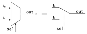
The multiplexers are combinational circuits with several inputs and a single data output. They are equipped with control inputs capable of selecting one, and only one, of the data inputs to allow its transmission from the selected input to said output.
In the field of electronics, the multiplexer is used as a device that can receive multiple inputs and transmit them over a shared transmission medium. To do this, what it does is divide the transmission medium into multiple channels, so that several nodes can communicate at the same time.
A signal that is multiplexed must be demultiplexed at the other end.
Depending on the way in which this division of the transmission medium is carried out, there are several kinds of multiplexing:
- Multiplexation by frequency division
- Multiplexing by time division
- Multiplexing by code division
- Multiplexing by wavelength division
Design in Digital Electronics
These combined circuits possess 2n{displaystyle 2^{n}} data entry lines, one output line and n selection tickets. Selection entries indicate which of these data entry lines is the one that provides the value to the output line. Each combination of selection inputs corresponds to a data input, and the final output of the multiplexor will correspond to the value of that selected input. To identify the most significant selection input, by agreement this is always the one that is above (to be shown vertically) or more to the left (to be horizontal), regardless of its identifier, unless otherwise specified.
You can also build multiplexers with a larger number of inputs using multiplexers with fewer inputs, using multiplexer composition.
In digital electronics, it is used to control a flow of information that is equivalent to a switch. In its most basic form it is made up of two data inputs (A and B), a data output, and a control input. When the control input is set to logic 0, the data signal A is connected to the output; when the control input is set to logic 1, the data signal B is the one that is connected to the output.
The multiplexer is a particular application of decoders, such that there is an enable input (EN) for each AND gate and at the end an OR is made between all the outputs of the AND gates.
The function of a multiplexer gives rise to various applications:
- Ticket selector.
- Serializer: Convert data from parallel format to serial format.
- Multiplexed transmission: Using the same connection lines, different data from different sources are transmitted.
- Realization of logical functions: Using investors and connecting to 0 or 1 entries according to interests, it is possible to design complex functions, in a more compact way than with traditional logical doors.
Contenido relacionado
Von Neumann architecture
ENIAC
Logical arithmetic unit
Commodore Amiga 4000
Motherboard

