
Microphone


A microphone (a word coined in the 18th century from the prefix micro-, «small» and the ancient Greek ϕωνήi - foné, «voice») is an input device used to transform sound waves into electrical energy and vice versa into sound recording and reproduction processes; It essentially consists of a diaphragm attracted by an electromagnet, which, when vibrating, modifies the current transmitted by the different pressures to a circuit. A microphone functions as an electroacoustic transducer or sensor, converting sound (sound waves) into an electrical signal for loudness, transmission, and recording. Microphones have multiple applications in different fields such as telephony, science, health, sound transmission in concerts and public events, sound transmission in mass media such as audiovisual productions (film and television), radio, live production and professional audio recording, sound engineering development, voice recognition and VoIP.
Most microphones today use electromagnetic induction (dynamic microphones), capacitance change (condenser microphones), or piezoelectricity (piezoelectric microphones) to produce an electrical signal from variations in air pressure. Microphones usually require being connected to a preamplifier ovary before their signal can be recorded or processed and reproduced on speakers or any sound amplification device.
History
Over time, humanity understood the need to develop more efficient and far-reaching communication tools. Thus, the desire to increase the volume of the words that sought to be transmitted was born. The oldest device to accomplish this dates from 600 B.C. c.; it was a mask with mouth openings that had a special acoustic design that increased the volume of the voice in amphitheatres. In 1665, the English physicist Robert Hooke was the first to experiment with an element such as air through the invention of the telephone. of tin that consisted of a wire attached to a cup at each of its ends.
In 1827, Charles Wheatstone first used the word "microphone" to describe an acoustic device designed to amplify weak sounds. Between 1870 and 1880 the history of the microphone and audio recordings began. The first microphone was part of the phonograph, which at the time was the most common device for reproducing recorded sound, and was known as the first dynamic microphone.
German inventor Johann Philipp Reis designed a rudimentary sound transmitter, which used a metal strip attached to a vibrating membrane and produced an intermittent current. In 1876 Alexander Graham Bell invented the telephone and for the first time included a functional microphone that used an electromagnet. This device was known as a 'liquid transmitter', with the diaphragm attached to a conductive rod in an acid solution. These systems, however, offered very poor sound pickup, prompting inventors to follow alternative paths of design.
Carbon Microphone

The first device that enabled quality communication was the carbon microphone (then called a transmitter), developed independently by David Edward Hughes in England and Emile Berliner and Thomas Edison in the United States. Although Edison obtained the first patent (after a long legal dispute) in mid-1877, Hughes managed to prove that his device had been developed for years, in the presence of many witnesses. In fact, most historians credit him with inventing it.
Hughes's device consisted of loosely packed carbon granules in a container where only air could enter. The acoustic waves exerted pressure on the carbon particles, which reacted and acted as a diaphragm, exerting a variable resistance to the passage of electric current due to its carbon content, allowing a relatively accurate reproduction of the sound signal. He did a demonstration of his apparatus to the Royal Society of London magnifying the sound of insects through a sound box. The main disadvantage of the device was that it lost sensitivity over time. Contrary to what the American inventor Thomas Alva Edison did, who applied for a patent on April 27, 1877 for his development, Hughes decided not to register the patent by donating his invention as a gift to the world.
The carbon microphone was the prototype that directly gave rise to the microphones that exist today and was fundamental in the development of the telephone, radio broadcasting, and entertainment industry.
For his part, Edison perfected the carbon microphone in 1886, simplifying it, achieving low-cost manufacturing, and making it highly efficient and durable. It became the basis for telephone transmitters used in millions of telephones around the world. This microphone was used in the first radio broadcast in history, a performance at the Metropolitan Opera House in 1910.
The next major step in transmitter design was in the hands of English inventor Henry Hunnings. He used coke pellets between the diaphragm and a metal plate for support. This design originated in 1878 and was patented in 1879. This transmitter was very efficient and could compete with any of its current competitors. Its only drawback was that it had a tendency to lose pickup sensitivity.
Other contributions
In 1916, Bell Laboratories developed the first condenser microphone.
The growth of the music and radio industry in the 1920s stimulated the development of higher quality carbon microphones. The year 1920 began the era of commercial advertisements in the mass media. Most of the communication professionals and high-profile entertainers like singers and stars started using the microphones in their respective fields.

In 1923 the first moving coil microphone with practical use was built. It was called the Marconi-Sykes tape recorder. Developed by Captain Henry Joseph Round, it was used in the BBC studios in London. This version of the microphone was improved in the 1930s by Alan Blumlein and Herbert Holman, who developed the HB1A, the best microphone at the time. In the same year, the ribbon microphone, another type of electromagnetic microphone, was released, believed to have been developed by Harry F. Olson by reverse-engineering an ancient speaker.
In 1931 Western Electric introduced the first dynamic microphone, the model 600, series 618.
Throughout the years, these microphones were developed by various companies, the greatest contributions to this technology were made by the RCA company, which introduced great advances in polar pattern control, to give directionality to the microphone pickup. Due to the rise of film and television, the demand for high fidelity microphones and greater directionality increased. The first microphone to be developed for the film industry was the PB17. It was an aluminum cylinder 17 inches long and 6 inches in diameter, its structure was magnetized and used an electromagnet that required a current of six volts and one ampere.
Already in the year 1947 an important event for the history of the microphone takes place: the AKG was founded in Vienna, an Austrian company that began to manufacture professional audio accessories, especially microphones and headphones. And in 1948 Neumann released the U47 tube microphone, the first condenser microphone with a polar pattern switchable between cardioid and omnidirectional. It ended up becoming a classic for recording voices since it became known that Frank Sinatra refused to sing without his U47.
In 1962 Hideo Matsushita established the Audio-Technica Corporation in Tokyo. The company released the AT-1 and AT-3MM models of stereo capsules and began supplying capsules to audio manufacturers. Later, in 1978, Audio-Technica released the ATH-8 and ATH-7 condenser headphones. These headphones have won several awards. This year also saw the development and launch of the 800 Series of microphones, and the creation of Audio-Technica Ltd. in Leeds, England.
The manufacturer Electro-Voice responded to the demands of the film industry by developing the "Shotgun microphone" or "Boom Mic" in 1963, which offered more focused audio pickup because it was unidirectional.
During the second half of the XX century, development in microphone technology advanced rapidly, when the Shure Brothers launched the models SM58 and SM57. The company Milab pioneered the digital age by launching the DM-1001 in 1999. Recent research includes the use of fiber optics, lasers, and interferometers.
Components and structure

Diaphragm
This is the most delicate part of a microphone. In some places it is also called a "pickup", although this term generally refers to the device that picks up vibrations in instruments such as an electric guitar. The diaphragm is a membrane that receives sound vibrations and is attached to the system that transforms these waves into electricity.
Transducer device (element or capsule)
The sensitive transducer device of a microphone is called an "element" or "capsule." This microphone capsule can be built in different ways and, depending on the type of transducer, microphones can be classified as dynamic, condenser, carbon or piezoelectric.
Grid
Protects the diaphragm. Avoid both sound shocks (the "p" and "b") as well as physical damage suffered by a fall.
Housing
It is the container where the microphone components are placed. In the handheld ones, which are the most common, this casing is made of light metals, light to carry but resistant when it comes to protecting the transducer device.
Microphone Types
Microphones are classified by their type of transducer, either condenser or dynamic, and by their directional characteristics. Sometimes other characteristics such as diaphragm size, intended use, or main sound input orientation are used to classify the microphone.
Condenser microphone

The "condenser microphone" was invented at Bell Laboratories in 1916 by Edward Christopher Wente. Also called an "electrostatic microphone" or "capacitance microphone" in these types of microphones the diaphragm acts as a plate that "condenses" the vibrations of the sound waves, which produce changes due to the variation of the distance between the diaphragm and the plate. There are two types, depending on the method of extracting the audio signal from the transducer: DC bias microphones, and shortwave or radio frequency (RF) condenser microphones.
In a CC polarization microphone, the plates are split with a fixed load (Q). The tension between the capacitor plates changes with vibrations in the air (according to the equation of the capacitance C=QV{displaystyle {C}={Q over V}}, where Q = load in assmbies, C = training in faradiums and V = potential difference in volts). The capacitance of the plates is inversely proportional to the distance between them for a condenser of parallel plates. The assembly of fixed and mobile plates is called an "element" or "capsula".

A nearly constant charge is maintained on the capacitor. With changes in capacitance, the charge across the capacitor changes very slightly, but at audible frequencies it is substantially constant. The capsule capacitance (around 5 to 100 pF) and the value of the bias resistor (100 mΩ to tens of GΩ) form a filter that is high-pass for the audio signal, and low-pass for the voltage. of polarization. Note that the time constant of an RC circuit is equal to the product of resistance and capacitance.
Within the time frame of the capacitance variation (as much as 50 ms at 20 Hz of an audio signal), the charge is practically constant and the voltage across the capacitor changes instantaneously to reflect the change in capacitance. The voltage across the capacitor varies above and below the bias voltage. The voltage difference between the bias and the capacitor is sensed through the series resistor. The voltage across the resistor is amplified to improve its performance or for recording. In most cases, the electronics in the microphone itself contribute to the voltage gain, so the voltage differential is quite significant, up to several volts for high sound levels. As it is a very high impedance circuit, the current gain is only what is necessary to modify the constant reference voltage.
RF Condenser Microphone

They use a comparatively low RF voltage, generated by a low-noise oscillator. The oscillator signal can either be amplitude modulated by capacitance changes produced by sound waves as the diaphragm or capsule moves, or the capsule can be part of a resonant circuit that modulates the frequency of the oscillator signal. Demodulation produces a low noise audio frequency signal, with a very low source impedance. The absence of a high bias voltage allows the use of a lower voltage diaphragm, which can be used to achieve the wider frequency response due to higher sensitivity. The RF bias process results in a lower electrical impedance capsule, allowing RF condenser microphones to operate in humid weather conditions, which could create problems in microphones using a DC-reference current with insulating surfaces. contaminated. The Sennheiser "MKH" uses RF push technique.
Condenser microphones run the gamut for phone transmitters as well as other uses, from low-cost karaoke microphones to high-fidelity recording microphones. They generally produce a high-quality audio signal and are now the standard choice of labs and recording studios. The inherent suitability of this technology is due to the very small mass that must be moved by the incident sound wave, unlike other types of microphones which require the sound wave to do more mechanical work. They require a power source, either through the microphone inputs on the equipment as auxiliary power or from a small battery. This current is necessary to establish the plate voltage of the power capacitor, and it is also necessary to power the microphone electronics (impedance conversion in the case of electret and DC-polarized microphones, demodulation or detection in the case of RF/HF). Condenser microphones are also available with two diaphragms that can be electrically connected to provide a range of polar patterns (see below), such as cardioid, omnidirectional, and figure-of-eight. It is also possible to vary the pattern continuously with some microphones (for example the Røde NT2000 or the CAD M179).
A valve microphone is a condenser microphone that uses an amplifying vacuum tube (valve). They remain popular with fans of vacuum tube sound.
Electret Condenser Microphone
An electret microphone is a type of condenser microphone invented by Gerhard Sessler and Jim West at Bell Laboratories in 1962. The application of an external charge described above in condenser microphones is replaced by a permanent charge on an electret material, a ferroelectric material that has been permanently electrically charged or polarized. The name comes from electrostatic and magnetet; a static charge is held together in an electret by the alignment of the static charges in the material, in the same way that a magnet's magnetism is made permanent by the alignment of the magnetic domains in a piece of iron.
Due to their good performance and ease of manufacture, therefore low cost, the vast majority of microphones made today are electret microphones; a semiconductor manufacturer estimates that annual production is more than a billion units. Almost all cell phones, computers, PDAs, and headsets are of the electret type. They are used in many applications, from high quality and lapel recording to the built-in microphones in small sound recording devices and telephones. Although electret microphones were initially considered of low quality, the best models of these microphones can now compete with traditional condenser models in all aspects and can even offer greater long-term stability and the ultra-flat response necessary for a microphone. measurement. Despite not requiring bias voltage, like other condenser microphones, they often contain an integrated preamplifier that requires power (often incorrectly called power or bias bias). This preamp is frequently phantom powered for sound reinforcement and studio applications. Some monophonic microphones designed for personal computers (PCs), sometimes called multimedia microphones, use a 3.5mm jack, as is typically used, without a power jack, for stereos; the connector, instead of carrying the signal for a second channel, carries electrical power through a resistor from (usually) a 5V supply in the computer. Stereo microphones use the same connector; there is no obvious way to determine which system is used by equipment and microphones.
Only the best electret microphones can rival other types of quality microphones in terms of noise level and quality. On the contrary, they lend themselves to low-cost mass production with acceptable features, which has led to their widespread use in all kinds of devices.
Dynamic microphone

Dynamic microphones (also known as magneto-dynamic microphones) work through electromagnetic induction. They are robust, relatively cheap, and resistant to moisture. This, along with their high gain potential before feedback, makes them ideal for stage use.
Moving coil microphones use the same dynamic principle that is used in a loudspeaker, but inverted. A small moving induction coil, located in the magnetic field of a permanent magnet, is attached to the membrane. When sound enters through the microphone grill, the sound wave moves the diaphragm, displacing the coil which moves in the magnetic field, which in turn produces a current variation in the coil through electromagnetic induction. A single dynamic membrane does not respond linearly at all audio frequencies. Some microphones for this reason use multiple membranes for different parts of the audio spectrum and the resulting signals are then combined. Correctly combining multiple signals is difficult, and designs capable of doing so are rare and tend to be expensive. On the other hand, there are various designs that more specifically target isolated parts of the audio spectrum. The AKG D 112, for example, is designed to respond to low sounds rather than high ones. In audio engineering, several types of microphones are often used at the same time to get the best result.
Ribbon microphone

Ribbon microphones use a thin (usually corrugated) metal ribbon suspended in a magnetic field. The tape is electrically connected to the microphone output, and its vibration within the magnetic field generates the electrical signal. Ribbon microphones are similar to coil microphones (both produce sound via magnetic induction). They detect sound in a bi-directional pattern (also called a figure-eight, as in the diagram below) because the tape is open on both sides, and because it has little mass, so it responds to air speed rather than to sound pressure. Although the balanced front and rear pickup can be a nuisance in normal stereo recording, high-side rejection can be used to advantage by placing a ribbon microphone horizontally, for example, above drum cymbals., so the rear lobe picks up only the sound of the cymbals. Crossed figure 8s, or Blumlein pairs, are gaining popularity in stereo recording, and the response arrangement of a figure-eight ribbon microphone is ideal for that application.
Other directional patterns can be produced by confining one side of the tape in a acoustic trap or baffle, allowing sound to come from only one side. The classic RCA Type 77-DX microphone has several externally adjustable positions of the internal baffle, allowing selection of various response patterns ranging from 'figure-of-eight' to 'figure-of-eight'; to "one-way". These older ribbon microphones, some of which still offer high-quality sound reproduction, were once highly prized for this reason, but could only achieve good low-frequency response when the ribbon was properly suspended, giving them made relatively brittle. The materials used in the headband have been modernized, including new nanomaterials, which has made it possible to make these microphones more reliable, and even improve their effective dynamic range at low frequencies. Protective windscreens can reduce the danger of damaging an old tape, and also reduce sonic pops on the recording. Properly designed windscreens produce negligible treble attenuation. Like other types of dynamic microphones, ribbon microphones do not require auxiliary power; in fact, this voltage can damage some older ribbon microphones. Some new modern ribbon microphone designs incorporate a preamplifier and therefore require auxiliary power. The circuits of modern passive ribbon microphones, that is, those without the aforementioned preamplifier, are specifically designed to resist damage to the ribbon and auxiliary power transformer. There are also new tape materials available that are immune to wind, sonic pops, and auxiliary power.
Carbon microphone

A carbon microphone, also known as a button microphone, uses a capsule or button containing carbon granules pressed between two metal plates like Berliner and Edison microphones. By applying a voltage across the metal plates, it causes a small electrical current to flow into the carbon. One of the plates, the diaphragm, vibrates in tune with the incident sound waves, applying variable pressure to the carbon granules. The change in pressure deforms the granules, causing the contact area between each pair of adjacent granules to change, and this causes the electrical resistance of the mass of granules to change. Changes in resistance produce a corresponding change in current flow through the microphone, producing the electrical signal. There was a time when carbon microphones were commonly used in telephony; they have extremely low sound reproduction quality and a very limited frequency response range, but they are very robust devices. Boudet's microphone, which uses relatively large carbon balls, was similar to granular carbon button microphones.
Unlike other types of microphones, the carbon microphone can also be used as a type of amplifier, using a small amount of electrical power. Originally, carbon microphones were used as telephone repeaters, making long-distance calls possible in the pre-vacuum tube era. These repeaters work mechanically, coupling a magnetic telephone receiver to the carbon microphone: the weak signal from the receiver was transferred to the microphone, where it was modulated into a strong electrical current, producing a strong electrical signal to send down the line. One consequence of this amplifying effect was oscillation produced by feedback, resulting in an audible squeal in early wall phones when the receiver was placed near the carbon microphone.
Piezoelectric microphone
.jpg)
A crystal microphone, or piezo microphone, uses the phenomenon of piezoelectricity—the ability of some materials to produce a voltage when subjected to pressure—to convert vibrations into an electrical signal. An example of this is sodium potassium tartrate, which is a piezoelectric crystal that works as a transducer (in the form of a slimline component), interchangeably as a microphone or as a loudspeaker. crystal microphones were commonly supplied with vacuum tube (valve) equipment, such as home tape recorders. Its high output impedance also matches the high impedance (typically about 10 megohms) of the vacuum tube input stage. They were hard to match in the early days of solid-state equipment, but were quickly replaced by dynamic microphones for a while, and later by small electret condenser devices. The high impedance of crystal microphones made them very susceptible to noise noise, both from the microphone itself and from the connecting cable.
Piezoelectric transducers are often used as contact microphones to amplify the sound of acoustic musical instruments, to detect drum hits, to trigger electronic samples, and to record sound in harsh environments, such as under high-pressure water.. Pickups mounted on acoustic guitars are generally piezoelectric devices in contact with the strings. This type of microphone is different from the magnetic coil pickups commonly seen on typical electric guitars, which use magnetic induction, rather than mechanical coupling, to pick up vibrations.
Fiber optic microphone

A fiber optic microphone converts acoustic waves into electrical signals by detecting changes in light intensity, rather than detecting changes in capacitance or magnetic fields, as with conventional microphones.
During operation, light from a laser source travels through an optical fiber to illuminate the surface of a reflective diaphragm. The sound vibrations of the diaphragm modulate the intensity of light that is reflected by the diaphragm in a specific direction. The modulated light is then transmitted via a second optical fiber to a photodetector, which transforms the intensity modulated light into analog or digital audio for transmission or recording. Fiber optic microphones have a high frequency and dynamic range, similar to that of the best conventional hi-fi microphones.
In addition, they are not influenced by electric, magnetic, electrostatic or radioactive fields (this is called EMI/RFI immunity). The fiber optic microphone design is therefore ideal for use in areas where conventional microphones are ineffective or dangerous, such as inside industrial turbines or in the environment of magnetic resonance imaging (MRI) equipment.
They are robust, resistant to environmental changes in temperature and humidity, and can be produced for any directionality or impedance matching. The distance between the microphone's light source and its photodetector can be up to several kilometers without the need for a preamplifier or any other electrical device, making fiber optic microphones suitable for industrial acoustic monitoring and surveillance.
They are used in very specific application areas, such as infrasound detection and noise cancellation. They have proven especially useful in medical applications, allowing radiologists, staff, and patients within the strong magnetic field and noisy environment in MRI rooms and control rooms to communicate normally. distance. Other uses include industrial equipment monitoring and audio detection, calibration and measurement, high-fidelity recording, and compliance with legally limited sound levels.
Laser microphone
Laser microphones often appear in movies as spy gadgets, as they can be used to pick up sound from a distance from the microphone equipment. A laser beam is directed at the surface of a window or other flat surface that is affected by sound. The vibrations of this surface change the angle at which the beam is reflected, allowing the movement of the laser beam point to be detected, which after returning to the equipment is converted into an audio signal.
In a more robust and expensive application, the returned light is split and fed to an interferometer, which detects surface motion by changes in the optical pathlength of the reflected beam. It is an experimental development; since it requires an extremely stable laser and very precise optics.
A new type of laser microphone is a device that uses a laser beam and smoke or steam to detect sound vibrations in the open air. On August 25, 2009, US Patent 7,580,533 issued for a particle flow detection microphone based on laser and photocell coupling, with a moving stream of smoke or vapor in the path of the laser beam. Sound pressure waves cause disturbances in the smoke, which in turn cause variations in the amount of laser light reaching the photodetector. A prototype of the device was demonstrated at the 127th Audio Engineering Society convention in New York on October 9–12, 2009.
Liquid microphone
Early microphones failed to reproduce speech intelligibly, until Alexander Graham Bell made improvements including a variable resistance between microphone and transmitter. Bell's liquid transmitter consisted of a metal container filled with water with a small amount of sulfuric acid added. A sound wave caused the diaphragm to move, forcing a needle to move up and down in the water. The electrical resistance between the wire and the container was then inversely proportional to the size of the water meniscus around the submerged needle. Elisha Gray advertised for a version with a brass rod instead of the needle. Other variants and minor improvements to the liquid microphone (devised by Majoranna, Chambers, Vanni, Sykes, and Elisha Gray) were introduced, and Reginald Fessenden patented his own version in 1903. These were the first microphones, but they were impractical for commercial application.. The famous first telephone conversation between Bell and Watson was carried out using a liquid microphone.
Microelectromechanical microphone (MEMS)
MEMS-type microphones ("Microelectromechanical systems" in English), are also called microphone chips or silicon microphones. A pressure sensitive diaphragm is etched directly onto a silicon wafer using MEMS processing techniques, and is usually accompanied with an integrated preamplifier. Most MEMS microphones are variants of the condenser microphone design. Digital MEMS has been built on integrated analog-to-digital circuitry (ADC) on the CMOS chip itself, making the chip a full digital microphone, more easily embeddable into modern digital products. Major manufacturers producing silicon MEMS microphones are Wolfson Microelectronics (WM7xxx) now Cirrus Logic, Analog Devices, Akustica (AKU200x), Infineon (product SMM310), Knowles Electronics, MemsTech (MSMx), NXP Semiconductors (a division purchased by Knowles), Sonion MEMS, Vesper, AAC Acoustic Technologies and Omron.
More recently, there has been increased interest and research in piezoelectric MEMS fabrication, which represents a significant change in architecture and materials from existing MEMS designs based on capacitor technology.
Speakers as microphones
A loudspeaker is a transducer that converts an electrical signal into sound waves. Functionally, it is the opposite of a microphone. Since conventional speakers are built much like a dynamic microphone (with a diaphragm, coil, and magnet), the speakers can actually work "in reverse" like microphones. The result, however, is a microphone with poor quality, limited frequency response (especially at the top end), and poor sensitivity. In practice, loudspeakers are sometimes used as microphones in applications where high quality and sensitivity are not required, such as intercoms, walkie-talkies, or video game voice chat peripherals, or where conventional microphones are in short supply.
However, there is at least one other practical application of this principle: the use of a medium-sized speaker placed in close proximity, in front of a drum kick pedal, to act as a microphone. The use of relatively large loudspeakers to transduce low-frequency sound sources, especially in music production, is becoming quite common. An example of such a device product is the Yamaha SUBKICK, a 6.5-inch (170 mm) subwoofer mounted in front of percussion instruments. Having a relatively heavy diaphragm, it is not capable of transducing high frequencies, so placing a speaker in front of a kick drum is often ideal for picking up the sound of the kick drum. Less commonly, the microphones themselves can be used as loudspeakers, almost always to reproduce high-pitched sounds. Microphones, however, are not designed to handle the power typically used to drive speakers. An example of such an application was "super tweeter" STC 4001, derived from a microphone. This device was used successfully in a number of high quality speaker systems from the 1960's through the mid 1970's.
Design and directionality of the capsule
The internal elements of a microphone are the main source of differences in directionality. A pressure microphone uses a diaphragm between a fixed internal volume of air and the environment, and responds evenly to pressure from all directions, thus it is said to be omnidirectional. A pressure gradient microphone uses a diaphragm that is at least partially open on both sides. The pressure difference between the two sides produces its directional characteristics. Other elements, such as the external shape of the microphone and external devices such as interference tubes, can also alter the directional response of a microphone. A pure pressure gradient microphone is equally sensitive to sounds coming from the front or rear, but insensitive to sounds coming from the side because sound coming in front and behind at the same time does not create a gradient between the two. The characteristic directional pattern of a pure pressure gradient microphone is like a figure 8. Other polar patterns are generated by creating a capsule that combines these two effects in different ways. The cardioid, for example, has a partially closed back, so its response is a combination of pressure and pressure gradient characteristics.
Polar pattern of a microphone
(Graphs of the different types of polar patterns):
 Omnidirectional
 Bidirectional or Figure 8
 Subcardiode
 Cardiode
 Hypercardioid
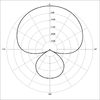 Supercardioid
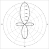 Shotgun


A microphone's directionality or polar pattern indicates how sensitive it is to sounds arriving at different angles around its central axis. The polar patterns illustrated above represent the locus of points that produce the same signal level output at the microphone if a given Sound Pressure Level (SPL) is generated from that point. The way the physical body of the microphone is oriented in relation to the diagrams depends on the microphone design. For large-diaphragm microphones like the Oktava (pictured above), the upward direction in the polar diagram is generally perpendicular to the body of the microphone, commonly known as the 'firing side'; or "side direction". For small diaphragm microphones, such as the Shure (also pictured above), it usually extends from the axis of the microphone commonly known as the "end fire" to the diaphragm. or "top/end direction".
Some microphone designs combine several principles in creating the desired polar pattern. This ranges from shielding the housing itself (meaning diffraction/dissipation/absorption), to electronically combining dual membranes.
Omnidirectional
The response of an omnidirectional (or non-directional) microphone is generally considered to be a perfect sphere in three dimensions. In the real world, this is not the case. As with directional microphones, the polar pattern of an "omnidirectional" is a function of frequency. The microphone body is not infinitely small and as a consequence tends to interfere in its own field with respect to sounds arriving from the rear, causing a slight flattening of the polar response. This flattening increases as the diameter of the microphone (assuming it is cylindrical) reaches the wavelength of the frequency in question. Therefore, the smallest diameter microphone gives the best omnidirectional characteristics at high frequencies.
The wavelength of sound at 10 kHz is just over an inch (3.4 cm). The smallest measurement microphones are usually 1/4" (6mm) in diameter, virtually eliminating directionality even at the highest frequencies. Omnidirectional microphones, unlike cardioids, do not use resonant cavities, so they can be considered the "purest" in terms of low coloration; they add very little distortion to the original sound. Being pressure sensitive can require a very flat low frequency response down to 20 Hz or below, so pressure sensitive microphones are also much less responsive to wind noise and plosives (velocity sensitive) than directional microphones..
An example of a non-directional microphone is the "8-Ball" model, which is designed as a black sphere.
One-way
A unidirectional microphone is sensitive to sounds from only one direction. The diagram above illustrates several of these patterns. In each diagram, the microphone is facing up. The sound intensity of a particular frequency is measured around the perimeter from 0 to 360°. Professional charts show these scales and include several graphs with different frequencies. The above diagrams only provide an overview of the typical shapes of the common patterns, and provide their names.
Cardioid

The most common unidirectional microphone is the cardioid microphone, so named because the sensitivity pattern is "heart-shaped," that is, a cardioid curve. The cardioid family of microphones are commonly used as vocal or speech microphones, as they are good at rejecting sounds from other directions. In three dimensions, the cardioid is in the shape of an apple, centered around the microphone which would be the "stem" of the Apple. The cardioid response reduces pickup from the rear and sides, helping to avoid feedback from the monitors. These microphones are directional with respect to the pressure gradient of the transducer, so placing them very close to the sound source (at distances of a few centimeters) results in increased bass. This is known as the 'proximity effect'. The SM58 has been the most widely used microphone for live vocals for over 50 years, demonstrating the importance and popularity of cardioid microphones.
A cardioid microphone is effectively a superposition of an omnidirectional microphone and a figure-of-eight microphone. With this arrangement, the sound waves coming from the rear, the negative signal of the device with figure 8 cancels the positive signal from the omni element, while for sound waves coming from the front, the two add to each other. A hypercardioid microphone is similar, but with a slightly larger figure-8, resulting in a narrower zone of front sensitivity and a smaller lobe of rear sensitivity. A supercardioid microphone is similar to a hypercardioid microphone, except that it has greater front sensitivity and even less rear sensitivity. While any pattern between omnidirectional and figure-8 is possible by adjusting their mix, common definitions state that a hypercardioid is produced by combining the two in a 3:1 ratio, yielding zero sensitivity at 109.5 °, while a supercardioid is generated with a 5:3 ratio, with zero sensitivity at 126.9°. The sub-cardioid microphone has no null points. It is produced at a ratio of approximately 7:3, with a level of 3-10 dB between the front and rear inputs.
Bidirectional
Microphones in "Figure of 8" or bi-directional microphones, receive sound equally from the front and rear of the element. Most ribbon microphones are of this type. In principle they do not respond to sound pressure at all, except for the change in pressure between the front and the back; since its arrival, the sound reaches the front and the rear equally, and there is no difference in pressure. Therefore, they do not respond to sound from that direction. In mathematical terms, while omnidirectional microphones are scalar transducers that respond to pressure from any direction, bidirectional microphones are vector transducers that respond to gradient along an axis normal to the plane of the diaphragm. This also has the effect of reversing the output polarity for sounds arriving from the rear side.
Shotgun, boom and parabolic microphones


Shotgun microphones are highly directional. Its directional pattern has a very narrow lobe in the forward direction and rejects sound from other directions. They have small sensitivity lobes on the left, right, and rear, but are much less sensitive to the rear than other directional microphones. This is a consequence of the element being placed at the rear end of a tube with slots cut along the side; Wave cancellation removes much of the off-axis sound. Due to their narrow area of sensitivity, shotgun microphones are commonly used on television and film cameras, in stadiums, and for field recording of wildlife. Parabolic microphones have similar features, but often have poorer bass response.
Limiters or "PZM"
Various approaches have been developed for the effective use of a microphone in non-ideal acoustic spaces, which often suffer from excessive reflections from one or more of the surfaces (boundaries) that make up the space. If the microphone is placed at, or very close to, one of these limits, surface reflections are not detected by the microphone. Initially this was done by placing a normal microphone adjacent to the surface, sometimes on a block of acoustically transparent foam. Sound engineers Ed Long and Ron Wickersham developed the concept of placing the diaphragm parallel and towards the border. Until the patent expires, the terms "Pressure Zone Microphone" and "PZM" They are still active brands of Crown International, so the generic phrase “Boundary Microphone” is preferred. While the boundary microphone was initially designed using an omnidirectional element, it is also possible to mount a directional microphone close enough to the surface to gain some of the benefits of this technique, while retaining the element's directional properties. Crown's trademark for this approach is called "Phase Coherent Cardioid" or "PCC", but there are other manufacturers that use this technique as well.
Specific Design Applications

A lavalier microphone is designed for hands-free operation. These small microphones are worn attached to people's clothing. Originally, they were attached with a lanyard around the neck, but more often they are attached to clothing with a clip, pin, tape, or magnet. The Lapel Cord can be concealed in clothing and connected to an RF transmitter stored in a pocket or attached to a belt (for mobile use), or it can be routed directly to the mixer (for stay-in-place applications).
A wireless microphone transmits audio as a radio or optical signal, rather than through a cable. It usually sends its signal using a small FM radio transmitter to a nearby receiver connected to the sound system, but it can also use infrared waves if the transmitter and receiver are within sight of each other.
A ceramic microphone picks up vibrations directly from a solid surface or object, as opposed to sound vibrations that are transmitted through the air. One use for these devices is to detect very low level sounds, such as small objects or insects. The microphone commonly consists of a magnetic transducer (moving coil), contact plate, and contact pin. The contact plate is placed directly on the vibrating part of a musical instrument or other surface, and the contact pin transfers the vibrations to the coil. Contact microphones have been used to pick up the sound of a snail beating and the footsteps of ants. A portable version of this microphone has recently been developed. A throat microphone is a variant of the contact microphone that picks up speech directly from a person's throat, to which it is attached. This allows the device to be used in areas with ambient sounds that would otherwise make speech inaudible.
A parabolic microphone uses a parabolic reflector to collect and focus sound waves onto a microphone receiver, much the same way a satellite dish (for example, a satellite dish) does radio waves. Typical uses for this microphone, which has unusually focused front sensitivity and can pick up sounds from many feet away, include wildlife recording, outdoor sporting events, eavesdropping, police investigations, and even espionage. Parabolic microphones are not typically used for standard recording applications, as they tend to have poor low-frequency response as a side effect of their design.
A stereo microphone integrates two microphones into one unit to produce a stereo signal. They are often used for broadcast or field recording applications, where it would be impractical to set up two separate condenser microphones in a classic X-Y configuration (see microphone practice) for stereo recording. Some of these microphones have an adjustable coverage angle between the two channels.
A noise canceling microphone is a highly directional design, intended for use in noisy environments. One of these uses is in aircraft cockpits, where they are typically installed as chin microphones next to headsets. Another use is in live music events, on concert stages with loud music, where they are used by live concert vocalists. Many noise canceling microphones combine the signals received from two diaphragms that are in opposite electrical polarity or are processed electronically. In dual-diaphragm designs, the main diaphragm is mounted closer to the desired source and the second is located further from the source so that it can pick up ambient sounds that will be subtracted from the main diaphragm signal. After the two signals have been combined, sounds other than the intended source are greatly reduced, substantially increasing the intelligibility of the processed sound. Other noise canceling designs use a diaphragm that is affected by the open ports on the sides and rear of the microphone, adding up to 16 dB of rejection of sounds that are farther away. Vocalists such as Garth Brooks and Janet Jackson have frequently used a single-diaphragm noise-cancelling headphone design. Some noise canceling microphones are throat microphones.
Stereo Microphone Techniques
Several standard techniques are used with microphones used in sound reinforcement systems in live performance, or for recording in a sound or film studio. By proper arrangement of one or more microphones, desirable characteristics of the sound to be picked up can be preserved while unwanted sounds are rejected.
Power supply
Microphones that contain active circuitry, like most condenser microphones, require power to operate the active components. The first of these microphones used vacuum tube circuitry with a separate power supply unit, using a multi-pole connector and cable. With the advent of solid-state amplification, power requirements were greatly reduced and it became practical to use the same cable conductors and connector for audio and power. Various feeding methods were developed during the 1960s, mainly in Europe. The two dominant methods were initially defined in German according to DIN 45595 standards as Tonaderspeisung or T-power and DIN 45596 for phantom power. Since the 1980s, phantom power has become much more common, because the same input can be used for powered and unpowered microphones. In consumer electronics such as DSLRs and camcorders, "power connection" is more common, for microphones that use a 3.5mm phone jack connector. The Phantom, T-power and plug-in power sources are described in the international standard IEC 61938.
Connectors

The most common connectors used by microphones are:
- XLR-3 male, in professional microphones.
- 1⁄4 inch (sometimes referred to as 6.35 mm), an analog audio connector used in the most economical music microphones, with an asymmetrical 1/4-inch TS phone connector (6.3 mm). Harmonic microphones commonly use a 1/4-inch high impedance TS connection (6.3 mm) connected to guitar amplifiers.
- 3.5 mm (sometimes referred to as 1/8 mini-pulgated), stereo (and also comes in varieties known as monkey) miniphone plug on digital cameras, recorders and microphones.
- Universal Serial Bus, which allows direct connection to computers. The electronics in these microphones powered through the USB connection performs preamplification and Analog/Digital conversion before the audio data is transferred through the USB connection.
Some microphones use other connectors, such as a 5-pin XLR or mini XLR for connection to portable equipment. Some lavalier microphones use a proprietary connector to connect to a wireless transmitter, such as a radio pack. Since 2005, professional quality microphones with USB connections, designed for direct recording to computer programs, began to appear.
Impedance
Microphones have an electrical characteristic called impedance, measured in ohms (Ω), which depends on their design. On passive microphones, this value describes the electrical resistance of the magnet coil (or similar mechanism). For active microphones, this value describes the output resistance of the amplifier circuitry. Usually, "nominal impedance" is set. Low impedance is considered to be 600 Ω. The average impedance is considered between 600 Ω and 10 kΩ. High impedance is greater than 10 kΩ. Due to their built-in electronic amplifier, condenser microphones typically have an output impedance between 50 and 200 Ω.
The output of a given microphone delivers the same power whether it is low or high impedance.[citation needed] If a microphone is manufactured in both high and low impedance versions impedance, the high impedance version has a higher output voltage for a given sound pressure input, and is suitable for use with vacuum tube guitar amplifiers, for example, which have a high input impedance and require a relatively high signal input voltage to overcome the inherent noise of the tubes. Most professional microphones are low impedance, around 200 Ω or less. The vacuum tube professional sound system incorporates a transformer that increases the impedance of the microphone circuit to the high impedance and voltage required to drive the input tube. External matching transformers are also available that can be used in line between a low impedance microphone and a high impedance input.
Low-impedance microphones are preferable to high-impedance ones for two reasons: One is that using a high-impedance microphone with a long cable results in high-frequency signal loss due to cable capacitance, which forms a low-pass filter with the output impedance of the microphone.[citation needed] The other is that long, high-impedance cables tend to pick up more stray signals in the form of interference electromagnetic. No damage occurs if the impedance between the microphone and other equipment does not match; the worst that can happen is a reduction in signal or a change in frequency response.
Some microphones are designed so that their impedance does not match the load they are connected to. In this case, their frequency response can be altered and cause distortion, especially at high pressure levels sonorous. Certain ribbon and dynamic microphones are exceptions to this behavior, as designers assume that a certain load impedance is part of the microphone's internal electroacoustic damping circuitry.
Digital Microphone Interfaces

The AES42 standard, published by the Audio Engineering Society, defines a digital interface for microphones. Microphones that conform to this standard directly output a digital audio stream through a male XLR or XLD connector, rather than producing an analog output. Digital microphones can be used with new equipment with appropriate input connections that comply with the AES42 standard, or through a suitable interface device. Studio-quality microphones operating in accordance with the AES42 standard are available in the ranges of various manufacturers.
Measurements and specifications

Due to differences in their construction, microphones have their own characteristic responses to sound. These differences produce different responses for non-uniform phases and frequencies. Also, microphones are not uniformly sensitive to sound pressure, and can accept different levels without distortion. Although microphones with as smooth a response as possible are desirable for scientific applications, this is often not the case for music recording, as a microphone's non-smooth response can produce desirable coloration of the sound. There is an international standard for microphone specifications, but few manufacturers adhere to it. As a result, comparison of published data from different manufacturers is difficult, because different measurement techniques are used. The Microphone Data website has compiled the complete technical specifications with images, response curves, and technical data from microphone manufacturers for each microphone currently listed, and even some obsolete models, and displays the data for all of them. in a common format for ease of comparison. However, care should be taken in drawing conclusions from this or other published data unless the manufacturer is known to have supplied specifications in accordance with IEC 60268-4.
A frequency response diagram shows the sensitivity of the microphone in decibels over a range of frequencies (typically 20 hertz to 20 kilohertz), typically for sound perfectly aligned with the microphone's axis (sound that goes to 0° at the capsule). The frequency response can be indicatively as follows: "30 Hz-16 kHz ± 3 dB". This is interpreted as a nearly flat, linear graph between the set frequencies, with variations in amplitude not more or less than 3 dB. However, it cannot be determined from this information how smooth the variations are, nor in which parts of the spectrum they occur. Note that commonly declared values such as "20 Hz-20 kHz" they are meaningless without a measure of tolerance in decibels. The frequency response of directional microphones varies greatly with distance from the sound source and with the geometry of the sound source. IEC 60268-4 specifies that the frequency response should be measured under "flat traveling wave" conditions (very far from the source), but this is rarely practical. “Close talk” microphones can be measured at different sound sources and distances, but there is no standard and therefore no way to compare data from different models unless the measurement technique is described.
Self noise, or equivalent input noise level, is the sound level that is created by the same microphone output voltage in the absence of sound. This represents the lowest point of the microphone's dynamic range, and is particularly important if you want to record sounds that are very weak. The measurement is often stated in dB(A), which is the equivalent volume of the noise on a frequency-weighted decibel scale of how the ear hears, for example: "15 dBA SPL" (SPL stands for Sound Pressure Level Relative to 20 Pascals.) The lower the number, the better. Some microphone manufacturers report the noise level using the ITU-R 468 noise-weighted standard, which more accurately represents how noise is perceived by the human ear, but gives a figure 11-14 dB higher. A quiet microphone typically provides 20 dBA SPL or 32 dB SPL 468 weighted. Very quiet microphones have been around for years for special applications, such as the Brüel & Kjaer 4179, with a noise level of 0 dB SPL. Recently, some microphones with low noise specifications have been introduced to the studio/entertainment market, such as models from Neumann and Røde that advertise noise levels of between 5-7 dBA. This is usually accomplished by altering the frequency response of the capsule and electronics to produce less noise within the A-weighted curve, while broadband noise can be increased.
The maximum SPL that the microphone can accept is measured for particular values of harmonic distortion (THD), typically 0.5%. This amount of distortion is generally inaudible, so you can safely use the microphone at this SPL without damaging the recording. Example: "142 Sound Pressure Peak (at 0.5% THD)". The higher the value, the better, although microphones with a very high maximum SPL also have higher self-noise.
Clip level is an important indicator of maximum usable level, as the generally quoted 1% THD figure under maximum SPL is actually a very mild level of distortion, quite inaudible, especially on short high peaks. The cut is much more audible. For some microphones, the clipping level can be much higher than the maximum SPL.
The dynamic range of a microphone is the difference in SPL between the noise floor and the maximum SPL. If set by itself, for example, "120 dB", it conveys significantly less information than self-noise and maximum SPL figures individually.
Sensitivity indicates how effectively the microphone converts acoustic pressure into output voltage. A highly sensitive microphone creates more voltage and therefore needs less amplification at the mixer or recording device. This is a practical concern but not directly an indication of a microphone's quality, and indeed sensitivity is a misnomer, transduction gain is perhaps more significant. (or just "output level") because true sensitivity is generally set by the noise floor, and too much "sensitivity" in terms of output level it compromises the clipping level. There are two common measurements. The international standard (preferred) is in millivolts per pascal at 1 kHz. A higher value indicates greater sensitivity. The older American method refers to a standard of 1 V/Pa and is measured in simple decibels, which translates to a negative value. Again, a higher value indicates higher sensitivity, so -60 dB is more sensitive than -70 dB.
Measuring microphones

Some microphones are designed to test speakers, measure noise levels, and quantify an acoustic experience. These are calibrated transducers and are usually supplied with a certificate of calibration stating absolute sensitivity vs. frequency. The quality of measurement microphones is often referred to by the designations "Class 1", "Type 2", etc., which are references not to microphone specifications but to sound level meters. A broader standard was adopted for describing the performance of measurement microphones.
Measurement microphones are generally scalar pressure sensors; they exhibit an omnidirectional response, limited only by the scattering profile of their physical dimensions. Sound intensity or sound power measurements require pressure gradient measurements, which are typically made with arrays of at least two microphones, or with anemometers.
Calibration
To make a scientific measurement with a microphone, you must know its precise sensitivity (in volts per pascal). Since this can change over the lifetime of the device, it is necessary to use regularly calibrated measurement microphones. This service is offered by some microphone manufacturers and certified independent test laboratories. Every calibrated measurement microphone is ultimately traceable to a primary standard to a national measurement institute, such as the NPL in the UK, the PTB in Germany, and the National Institute of Standards and Technology in the US, which most commonly calibrate using a primary standard of reciprocity. Measurement microphones calibrated with this method can be used to calibrate other microphones using calibration comparison techniques.
Depending on the intended application, measurement microphones should be tested periodically (usually every year or several months) and after any potentially damaging event, such as being dropped (most of these microphones come in padded cases with foam to reduce this risk) or sound exposure beyond the acceptable level.
Microphone Arrays
A microphone array is any group of microphones that work in tandem. They have many applications:
- Systems to separate voice sources and environmental noise (especially telephones, speech recognition systems or hearing aids).
- Enveloping sound and related technologies.
- Location of objects by sound, such as military use to locate the origin of artillery fire, or the location and tracking of aircraft.
- Original recordings of high fidelity.
- Sound beam conforming for localized acoustic detection of subcutaneous tissues.
Typically, an array is made up of omnidirectional microphones distributed around the perimeter of a space. They are connected to a computer that records and interprets the results in a consistent way.
Anti-wind and anti-acoustic blast protection


Acoustic pop or wind protectors provide a method of reducing the effect of wind on microphones. While the deflector screens provide protection against unidirectional sound micro-explosions, the foam windscreens protect the grill from wind from all directions. Other systems completely wrap around the microphone and protect your body as well. The latter is important because, given the extreme low frequency content of wind noise, induced vibration in the microphone housing can contribute substantially to noise formation.
The shielding material used—wire mesh, cloth, or foam—is designed to have significant acoustic impedance. The relatively low pressure variations of the low-velocity particulate air that make up sound waves can pass through the screen with minimal damping, but the high-velocity particulate air is impeded to a greater extent. Increasing the thickness of the material improves wind damping but also begins to compromise high-frequency sound. This limits the practical size of simple foam screens. While foams and wire mesh can be partially or fully self-supporting, soft fabrics and woven mesh require being stretched over a frame or supported with thicker structural elements.
Since all wind noise is generated at the first surface the air strikes, the greater the space between the periphery of the windscreen or screen and the microphone capsule, the greater the noise attenuation. For a roughly spherical windshield, the damping increases by about a cube of that distance. Therefore, larger windshields are always much more efficient than smaller ones. With full-basket windshields there is an additional pressure chamber effect, first explained by Joerg Wuttke, which, for two-stage microphones ports (pressure gradient), allows the windscreen/microphone combination to act as an acoustic high-pass filter.

Since turbulence over a surface is the source of wind noise, reducing raw turbulence can increase noise reduction. Aerodynamically smooth surfaces, and those that prevent powerful vortices from being generated, are both often used successfully. Historically, fur or artificial hair has proven to be very useful for this purpose, since its fibers produce microturbulence and silently absorb energy. If not protected against wind and rain, fur or pile fibers are very acoustically transparent, but a fabric backing can provide significant damping. As a material, it is difficult to manufacture with consistency and to keep in perfect condition. For this reason, its use tends to be avoided (DPA 5100, Rycote Cyclone).
In the studio and on set, baffle screens and foam windscreens can be useful for hygienic reasons and to protect microphones from saliva and sweat. Also, with their colors and personalization they can be useful as identifiers. Instead, the basket protector may contain a suspension system to isolate the microphone from noise produced by shocks received during handling.
Establishing the efficiency of wind noise reduction is an inexact science, as the effect varies enormously with frequency, and therefore with the bandwidth of the microphone and audio channel. At very low frequencies (10-100 Hz), where there is massive wind energy, reductions are important to avoid overloading the audio chain, particularly in the early stages. This can produce the typical “wump” sound associated with wind, which is often muted due to low frequency peak limiting. At higher frequencies - 200 Hz to ~3 kHz - the hearing sensitivity curve allows wind effect to be heard as an addition to ambient sound, even though it has a much lower energy content. Simple windscreens can allow wind noise to be reduced by 10 dB; the best ones can achieve attenuation of more than 50 dB. However, acoustic transparency should also be noted, particularly at high frequency, as a very high level of wind attenuation could be associated with muffled or weak sound.
Classification of microphones
Microphones can be divided according to several classifications:
- According to his guide
- According to the transducer
- According to its usefulness
- According to their quality
According to directivity

As mentioned in the characteristics there are six types of microphones:
- omnidirectional microphone
- Pressure zone microphone
- Bidirectional microphone
- Pressure gradient microphone
- Unidirectional microphone of interference, line, rifle, cannon or semicron.
- Parabolic microphone
According to the confinement of the diaphragm
Three groups are established:
- Pressure microphone
- Pressure or speed gradient microphone
- Combined pressure microphone and pressure gradient
According to its mechanical-electrical transduction
The 6 most important types of microphones are:
- Electrostatic microphone: capacitor, electroret, etc.
- Dynamic microphone: coil and tape
- Micrófono piezoeléctrico
- Magnetic microphone
- Magnetic microphone
- Carbon microphone
According to its utility

There are six types of microphones according to their use:
- Hand microphone or cane: Designed to be used subject with hand. It is designed so that it cushions the blows and noises of manipulation.
- Study microphone: They do not have protection against manipulation, but they are placed in a fixed position and protected by rubber against vibrations.
- Contact microphone: They take the sound by being in physical contact with the instrument. It is also used to shoot a sound from a module or sampler through a trigger MIDI.
- Micrófono de solapa, tie or Lavalier. Miniature microphone that has filters to avoid the low frequencies that produces the roce of the device with the clothes.
- Wireless microphone: The particularity of this device is the possibility of using it without cable. They can be of flap or cane (handed). They do not need the cable by owning an FM transmitter (more common than one AM).
- Mega directional microphone: Microphone with a recording area of 50 cm. It serves to record a single person or source from larger distances.
Contenido relacionado
NetBEUI
PicoBSD
Lynx (browser)