
History of optics
The earliest applications of optics most likely began with the development of lenses in ancient Egypt and Mesopotamia. The earliest known lenses, made of polished glass, often quartz, date as early as 700 BC. C., like the Nimrud lens, discovered in Assyria. Water-filled glass spheres used as lenses in ancient Rome and ancient Greece are also known. The invention of these objects was followed by the emergence of theories of light and vision put forward by ancient Greek and Indian philosophers, and by the development of geometrical optics in the Greco-Roman world. The word optics comes from the Greek word ὀπτική (optikē), which means "aspect, appearance".
Greek philosophy of optics divided into two opposing ideas of how sight worked: the "vision theory" and the "emission theory".
The first approach considered that vision came from the objects themselves. According to the Aristotelian theory of vision, sensations are realized through a medium, such as air or water. These are transparent, as a possibility or power. Transparency update is light; light is therefore a state of the transparent as such rather than a movement, and its appearance is instantaneous. Aristotle believed that light was a kind of disturbance in the air. However, according to Aristotle, light does not travel or move, but is a presence that pervades space. Atomists such as Democritus, Epicurus, and their followers held that objects that emitted images of themselves (called eidola) that were captured by the eye.
Plato was the first to articulate the emission theory, the idea that vision is achieved by rays emitted from the eyes. He also discussed mirror inversion (of the parity between an object and its reflected image) in the Timaeus. About a hundred years later, Euclid wrote a treatise called Optics, where he linked vision to geometry, creating geometrical optics. In his work on Plato's emission theory he described the mathematical rules of perspective and described the effects of refraction qualitatively, although he disputed that a ray of light emitted from an eye would instantly illuminate the stars every time someone blinked.
Claudius Ptolemy, in his treatise on Optics, introduced a theory of vision that combined the previous two: the rays (or flux emitted) from the eye formed a cone, the vertex was inside the eye, and the base defined the visual field. The rays were sensitive and conveyed information to the observer's intellect about the distance and orientation of surfaces. He summarized much of Euclid's work and described a way to measure the effects of Snell's law, although he did not realize the empirical relationship between the angles.
During the Middle Ages, Greek ideas about optics were revived and expanded by various writers in the Islamic world. One of the earliest was Al-Kindi (c 801-73), who wrote on the merits of Aristotelian and Euclidean ideas in optics, favoring the emission theory as it could better quantify optical phenomena. In 984, Iranian mathematician Ibn Sahl wrote the treatise "On Incendiary Mirrors and Lenses", correctly describing a law of refraction equivalent to Snell's law. He used this law to calculate optimal shapes for curved mirrors and lenses. At the beginning of the s. xi AD C., Alhacén, considered one of the fathers of optics, wrote the Book of Optics (Kitab al-manazir) in which he explored reflection and refraction and proposed a new system for explaining vision and light based on observation and experiment. He rejected the "emission theory" of Ptolemaic optics with its emitted rays by the eye, and put forward the idea that light is reflected in all directions in straight lines from all points of viewed objects and then enters the eye, although he was not able to explain correctly how the eye caught the rays. Alhacén's work was largely ignored in the Arab world, but was anonymously translated into Latin around 1200 and later summarized and expanded upon by the Polish monk Witelo,becoming a standard text on optics in Europe for the next 400 years.
in 13th -century medieval Europe, the English bishop Roberto Grosseteste wrote on a wide range of scientific topics and discussed light from four different perspectives: an epistemology of light, a metaphysics or cosmogony of light, an aetiology or physics of light and a theology of light, drawing on the works of Aristotle and Platonism. Grosseteste's most famous disciple, Roger Bacon, wrote works citing a wide range of optical and philosophical works then in translation, including Alhacen, Aristotle, Avicenna, Averroes, Euclid, al-Kindi, Ptolemy, Tideus, and Constantine the African.. Bacon was able to use parts of glass spheres as magnifying glasses to show that light reflects off objects rather than being released from them.
The first practical eyeglasses were invented in Italy around 1286. This was the beginning of the optical industry of polishing lenses for these eyepieces, first in Venice and Florence in the 13th century, and later in eyeglass manufacturing centers in the Netherlands and Germany. Spectacle manufacturers created improved types of lenses for vision correction, based more on the empirical knowledge gained by observing the effects of the lenses than on using the rudimentary optical theory of the time (optical theory). he couldn't even adequately explain how the glasses worked).The practice of developing, mastering and experimenting with lenses led directly to the invention of the compound light microscope around 1595 and the refracting telescope in 1608. Both appeared in eyeglass manufacturing centers in the Netherlands.
Around the year 1600, Galileo Galilei directed his primitive refracting telescope towards the sky, giving rise to modern astronomy, which could use magnifying instruments to see the details of celestial bodies. Following in his footsteps, at the beginning of the 17th centuryJohannes Kepler expanded geometrical optics in his writings, covering lenses, reflections from plane and curved mirrors, the principles of the pinhole camera, the inverse square laws governing the intensity of light, and optical explanations of astronomical phenomena such as lunar and solar eclipses and astronomical parallax. He was also able to correctly deduce the role of the retina as the actual organ that perceives images, and was finally able to scientifically quantify the effects of the different types of lenses that eyeglass manufacturers had been looking at for the past 300 years. After the telescope was invented, Kepler laid the theoretical groundwork for how it worked and described an improved version, known as the Keplerian telescope., using two convex lenses to produce higher magnification.
Optical theory progressed in the mid-17th century with treatises written by the philosopher René Descartes, in which he explained a wide variety of optical phenomena, including reflection and refraction by assuming that light was emitted by the objects that produced it.This interpretation differed substantially from the ancient Greek emission theory. In the late 1660s and early 1670s, Isaac Newton expanded Descartes' ideas into a corpuscular theory of light, determining that white light was a mixture of colors that can be separated into its component parts with a prism. In 1690, Christiaan Huygens proposed a wave explanation for light, building on suggestions made by Robert Hooke in 1664. Hooke himself publicly criticized Newton's theories of light, and the dispute between the two lasted until Hooke's death. In 1704, Newton published Opticks, and at the time, partly due to his success in other areas of physics, he was generally considered the winner in the debate over the nature of light.
Meanwhile, optical instruments began to undergo considerable technical improvements, allowing science to enter hitherto inaccessible fields, from the extremely small (represented by the discovery of microbes) to the inconceivably large (with ever-increasing knowledge of the system). solar). The microscope, considerably evolved from the primitive model of Anton van Leeuwenhoek (1650), allowed the study of cells to begin thanks to the pioneering work of Robert Hooke, collected in his treatise Micrographia. On the other hand, refracting telescopes had reached their theoretical limit of resolution, limited by chromatic aberration, which in part contributed to the birth of a new type of instrument: the reflecting telescope. It was Isaac Newton who built the first of these instruments in 1668. This was the beginning of a bitter race, which lasted two and a half centuries, between the two types of telescopes: refractors (lenses) and reflectors (mirrors). The invention of achromatic lenses around 1750 made it possible to solve the problem of chromatic aberration, which initially gave primacy to refracting telescopes over primitive reflecting telescopes, weighed down by the low luminance and poor durability of speculum mirrors, a bronze alloy that oxidized relatively easily. xviii, becoming the dominant technique in the xix century. It was also Fraunhofer who would lay the foundations for a new science that is part of optics: spectroscopy. Advances in the manufacture of lenses in turn allowed the development of instruments used in geodesy, making it possible to complete the measurement of the Paris meridian arc in 1798 with a hitherto unthinkable precision, which would allow the establishment of the unit of length of the international system: the subway.
Newtonian optics was generally accepted until the early 19th century, when experiments on the interference of light were carried out by Thomas Young and Augustin Fresnel, which firmly established its wave nature. Young's famous double-slit experiment, which revealed the phenomenon of interference, showed that light follows the principle of layer superposition, which is a wave property not anticipated by Newton's corpuscular theory. This work led to a theory of the diffraction of light and opened up a whole area of study in physical optics. Wave optics was successfully unified with electromagnetism by James Clerk Maxwell in the 1860s.
The second half of the 19th century saw a series of discoveries that would lay the foundations for the development of optical instruments throughout the 20th century. In the field of telescopes, the possibility of depositing an aluminum film on a glass base definitively decided the race between the two types of telescopes, deciding in favor of those with mirrors, which have continued to increase in size without cease ever since. Likewise, the basis of photography was discovered with the works of Niépce, which in turn would lead to the appearance of cinema a few decades later. Another late 19th century invention, the cathode ray tube, would allow television screens to be developed a few years later. In this period another type of scientific instrument also came to light, the interferometer, which served to give unexpected support to the theory of relativity and which, over time, has become part of extremely high-precision measurement equipment, such as LIGO, which has confirmed the existence of gravitational waves at the beginning of the 21st century.
The apparent confirmation of the wave nature of light due to its character of electromagnetic radiation, led to a dead end, generating an intense debate for half a century about the existence of the ether, a hypothetical medium that was considered essential for allow the propagation of light waves. Numerous experiments were carried out unsuccessfully to prove its existence (such as the famous Michelson and Morley experiment of 1887), and it was not until 1905 that Albert Einstein, with his Theory of Special Relativity, established the key role of the speed of light as one of the fundamental constants of nature, resolving once and for all the question of the ether, definitively ruling out its existence.
The next development in optical theory came in 1899, when Max Planck correctly modeled blackbody radiation by assuming that energy exchange between light and matter only occurred in discrete quantities that he called quanta. In 1905 Albert Einstein published the theory of the photoelectric effect which firmly established the quantization of light itself. In 1913 Niels Bohr showed that atoms could only emit discrete amounts of energy, which explains the discrete lines seen in emission and absorption spectra.The understanding of the interaction between light and matter that followed these developments not only formed the basis of quantum optics, but was also crucial to the development of quantum mechanics as a whole. The last culmination, the quantum electrodynamic theory, explains all optical and electromagnetic processes in general as a result of the exchange of real particles and virtual photons.
Quantum optics gained practical importance with the inventions of the maser in 1953 and the laser in 1960. Following the work of Paul Dirac on quantum field theory, George Sudarshan, Roy Jay Glauber, and Leonard Mandel applied quantum theory to the electromagnetic field in the 1950s and 1960s to gain a more detailed understanding of photodetection and the statistical behavior of light.
Another important milestone in the field of practical application of optical devices are LEDs, whose operating principle (electroluminescence) was discovered in 1903. They began to be produced industrially in the 1950s, until they became ubiquitous in screens of all kinds. of mass consumption devices, such as mobile phones or televisions.
Classic optics
Classical optics is divided into two main branches: geometric (or ray) optics and physical (or wave) optics. In geometrical optics, light is considered to travel in a straight line, while in physical optics, light is considered as an electromagnetic wave.
Geometric optics
Geometrical optics can be viewed as an approximation to physical optics that applies when the wavelength of light used is much smaller than the size of the optical elements in the system being analyzed. geometrical optics, or ray optics, describes the propagation of light in terms of "rays" that travel in straight lines, and whose paths are governed by the laws of reflection and refraction in phase changes between different media. These empirically discovered laws have been widely used in the design of optical components and instruments.
The laws of reflection and refraction can be derived from Fermat's principle, which states that "the path traveled between two points by a ray of light is the path that can be traversed in the shortest possible time.
Approximations
Geometrical optics is often simplified by making a paraxial approximation or "small angle approximation". Mathematical behavior becomes linear, allowing optical components and systems to be described by simple matrices. This leads to the techniques of Gaussian optics and paraxial ray tracing, which are used to determine the basic properties of optical systems, such as the approximate images and positions of objects and the corresponding optical magnification.
Reflection

Reflection can be divided into two types: mirror image and diffuse reflection. Specular reflection describes the sheen of surfaces such as mirrors, which reflect light in a simple and predictable way. This enables the production of reflected images that can be associated with a real (real) or extrapolated (virtual) location in space. Diffuse reflection describes non-shiny materials, such as paper or rocks. Reflections from these surfaces can only be described statistically, with the exact distribution of reflected light depending on the microscopic structure of the material. Many diffuse reflectors are described or can be approximated by Lambert's law, which describes surfaces that have equal luminance when viewed from any angle.
In specular reflection, the direction of the reflected ray is determined by the angle that the incident ray makes with the normal vector, a line perpendicular to the surface at the point where the ray is incident. The incident and reflected rays and the normal lie in a single plane, and the angle between the reflected ray and the surface normal is the same as that between the incident ray and the normal. This physical phenomenon is known as a mirror image.
For plane mirrors, the law of reflection implies that the images of the objects are upright and the same distance behind the mirror as the objects in front of the mirror. The size of the image is the same as the size of the object. The law also implies that the mirror images have an inverted parity, which is perceived as a left-right inversion. Images formed from reflection in two (or any even number of) mirrors are not parity inverted. A corner reflector is a retroreflector that produces reflected rays that travel in the same direction (and different directions) from which the incident rays came.
Curved mirrors can be modeled using ray tracing and using the law of reflection at each point on the surface. In parabolic mirrors, rays parallel to the axis incident on the mirror produce reflected rays that converge to a common focus. Other curved surfaces can also focus light, but with aberrations due to the divergent shape causing the focus to spread out in space. In particular, spherical mirrors exhibit spherical aberration. Curved mirrors can form images with a magnification greater or less than one, and the magnification can be negative, indicating that the image is inverted. A vertical image formed by reflection in a mirror is always virtual, while an inverted image is real and can be projected on a screen.
Refraction
Refraction occurs when light travels through an area of space that has a changing index of refraction; this principle allows to build lenses capable of focusing light. The simplest case of refraction occurs when there is an interface between a uniform medium with index of refraction 


where 

The refractive index of a medium is related to the speed v, of light in that medium by
where c is the speed of light.
Snell's law can be used to predict the deflection of light rays as they pass through linear media, provided the refractive indices and geometry of the media are known. For example, the propagation of light through a prism results in the light ray bending depending on the shape and orientation of the prism. In most materials, the refractive index varies with the frequency of light. Taking this into account, Snell's law can be used to predict how a prism will scatter light in a spectrum.
Some media have a refractive index that varies gradually with position, and therefore light rays in the medium are curved. This effect is responsible for the mirages seen on hot days: a change in the refractive index of air aloft causes light rays to bend, creating the appearance of specular reflections in the distance (as if they were on the surface of a expanse of water). Optical materials with variable refractive index are called refractive index gradient (GRIN) materials. Such materials are used to make instruments according to the principles of index gradient optics.
For light rays traveling from a material with a high refractive index to a material with a low refractive index, Snell's law predicts that it
Glasses
A device that produces converging or diverging light rays due to refraction is known as a "lens." Lenses are characterized by their focal length: a converging lens has a positive focal length, while a diverging lens has a negative focal length. A smaller focal length indicates that the lens has a stronger converging or diverging effect. The focal length of a simple lens in air is given by the configuration of the lens itself.
Ray tracing can be used to show how images are formed with a lens. For a thin lens in air, the location of the image is given by the simple equation:
where 


Incoming parallel rays are focused by a converging lens to a point one focal length from the lens, on the far side of the lens. This is called the rear focal point of the lens. Rays from an object at a finite distance are focused further from the lens than the focal length; the closer the object is to the lens, the farther the image is from the lens.
With diverging lenses, the incoming parallel rays diverge after passing through the lens, so that they appear to have originated at a point a focal length in front of the lens. This is the front focal point of the lens. Rays from an object at a finite distance are associated with a virtual image that is closer to the lens than the focal point, and on the same side of the lens as the object. The closer the object is to the lens, the closer the virtual image is to the lens. As with mirrors, the upright images produced by a single lens are virtual, while the inverted images are real.
Lenses suffer from aberrations that distort images. Monochromatic aberrations occur because the geometry of the lens does not direct the rays from every point on the object to a single point in the image, while chromatic aberration occurs because the refractive index of the lens varies with the wavelength of light..
Physical optics
In physical optics or wave optics, light is considered to propagate as a wave. This model predicts phenomena such as interference and diffraction, which are not explained by geometrical optics. The waves propagate in the Earth's atmosphere at almost the same speed of light in a vacuum, approximately 3.0×10 m/s (exactly 299,792,458 m/s in a vacuum). The wavelength of visible light waves varies between 400 and 700 nanometres, but the term "light" is also frequently applied to infrared radiation (0.7-300 μm) and ultraviolet radiation (10-400 nm).). The wave model can be used to make predictions about how an optical system will behave without requiring an explanation of what medium the waves are "stirring" about. Until the mid-19th century, most physicists believed in an "ethereal" medium in which the light disturbance propagated. The existence of electromagnetic waves was predicted in 1865 by Maxwell's equations. These waves propagate at the speed of light and exhibit variable electric and magnetic fields that are orthogonal to each other, and also to the direction of propagation of the waves. Currently, light waves are treated as electromagnetic waves, except when must consider quantum mechanical effects.
Modeling and design of optical systems using physical optics
Many simplified approaches are available to analyze and design optical systems. Most use a single scalar quantity to represent the electric field of the light wave, rather than using a vector model with orthogonal electric and magnetic vectors.
The Fresnel-Huygens principle is one such model, derived empirically by Fresnel in 1815, based on Huygens's hypothesis that each point on a wavefront generates a secondary spherical wavefront, which Fresnel combined with the superposition principle of waves. Kirchhoff's diffraction formula, which is derived from Maxwell's equations, puts the Huygens-Fresnel equation on a firmer physical footing. Examples of the application of the Huygens–Fresnel principle can be found in the diffraction and Fraunhofer diffraction sections.
More rigorous models, involving modeling of light wave electric and magnetic fields, are required when dealing with the detailed interaction of light with materials where the interaction depends on their electric and magnetic properties. For example, the behavior of a light wave interacting with a metal surface is quite different from what happens when it interacts with a dielectric material. A vector model must also be used to model polarized light.
Numerical simulation techniques, such as the finite element method, the boundary element method, and the linear transmission matrix method, can be used to model the propagation of light in systems that cannot be solved analytically. Such models are computationally demanding and are typically only used to solve small-scale problems that require greater precision than can be achieved with analytical solutions.
All the results of geometric optics can be reproduced using Fourier optics techniques, which apply many of the same mathematical and analytical techniques used in acoustic engineering and signal processing.
Gaussian beam propagation is a simple paraxial physical optics model for dealing with the propagation of coherent radiation, such as lasers. This technique partially explains diffraction, allowing precise calculations of the rate at which a laser beam expands with distance and the minimum size to which the beam can be focused. Gaussian beam propagation bridges the gap between geometric optics and physics.
Overlap and interference
| combined waveform |  | |
| Then 1 | ||
| Then 2 | ||
| Two wavesin phase | Two waves180° out of phase |
In the absence of nonlinear effects, the superposition principle can be used to predict the configuration of interacting waveforms by simply summing the perturbations. This interaction of waves to produce a resulting pattern is usually called "interference" and can result in a wide variety of results. If two waves of the same wavelength and frequency are in phase, the crests and troughs of the waves line up. This results in interference, with an increase in wave amplitude, which for light is associated with a brightness of the waveform at that location. Alternatively, if the two waves of the same wavelength and frequency are out of phase, the wave crests will align with the troughs of each wave and vice versa. This results in interference with a decrease in wave amplitude, which for light is associated with a darkening of the waveform at that location. See below for an illustration of this effect.
Since the Fresnel-Huygens Principle states that each point on a wavefront is associated with the production of a new disturbance, it is possible for a wavefront to interfere constructively or destructively at different locations, producing bright and dark fringes on the wavefront. regular, predictable patterns. Interferometry is the science of measuring these patterns, usually as a means of making precise determinations of distances or optical resolutions. The Michelson interferometer is a famous instrument that used interference effects to accurately measure speed of light.
The appearance of thin films and coatings is directly affected by interference effects. Glare suppression uses destructive interference to reduce the reflectivity of the surfaces they coat, and can be used to minimize unwanted glare and reflections. The simplest case is a single layer with a thickness of a quarter of the wavelength of the incident light. The reflected wave from the top of the film and the reflected wave from the film/material interface are exactly 180° out of phase, causing destructive interference. The waves are only exactly out of phase for a given wavelength, which is typically chosen to be near the center of the visible spectrum, around 550nm.
Constructive interference in thin films can create a strong reflection of light over a range of wavelengths, which can be narrow or wide depending on the design of the coating. These films are used to make dielectric mirrors, interference filters, heat reflectors, and color separation filters in color television cameras. This interference effect is also what causes the colorful rainbow patterns seen in oil slicks and soap bubbles.
Diffraction and optical resolution
Diffraction is the process by which the interference of light is most commonly observed. The effect was first described in 1665 by Francesco Maria Grimaldi, who also coined the term from the Latin diffringere, for "breaking into pieces". Later in the century, Robert Hooke and Isaac Newton also described phenomena now known as Newton's ring diffraction, while James Gregory recorded his observations on the diffraction patterns of bird feathers.
The first diffraction model using physical optics was based on the Fresnel-Huygens principle, and was developed in 1803 by Thomas Young through his double-slit experiment, analyzing the interference patterns of two closely spaced slits. He showed that his results could only be explained if the two slits acted as single wave sources rather than corpuscles. In 1815 and 1818, Augustin Fresnel firmly established the mathematics of how wave interference can explain diffraction.
The simplest physical models of diffraction use equations that describe the angular separation of light and dark fringes due to light of a particular wavelength (λ). In general, the equation takes the form

where 


This equation is slightly modified to account for a variety of situations such as diffraction through a single gap, diffraction through multiple slits, or diffraction through a diffraction grating containing a large number of equal slits. spacing. More complicated diffraction models require working with Fresnel or Fraunhofer mathematics.
X-ray crystallography makes use of the fact that the atoms in a crystal are regularly spaced at distances that are on the order of one angstrom. To see the diffraction patterns, X-rays with wavelengths similar to that spacing are passed through the crystal. Since crystals are three-dimensional objects rather than two-dimensional gratings, the associated diffraction pattern varies in two directions according to Bragg's law, and the associated bright spots occur in unique patterns and
The effects of diffraction limit the sensitivity of an optical detector to the separation between two light sources, determining its optical resolution. In general, light passing through an aperture will experience diffraction, and the best images that can be created through this aperture (as described in a diffraction-limited system) appear as a central point with surrounding bright rings, separated by dark stripes; this pattern is known as an Airy disk. The size of such a disk is given by

where θ is the angular resolution, λ is the wavelength of light, and Dis the diameter of the lens aperture. If the angular separation of the two points is significantly less than the angular radius of the Airy disk, then the two points cannot be resolved into the image, but if their angular separation is much greater than this, then distinct images of the two are formed. points and therefore can be solved. Rayleigh arbitrarily defined "optical resolution" as the two points whose angular separation is equal to the radius of the Airy disk (measured to the first null ring, that is, to the first place where no light is seen) that can be considered resolved. It can be seen that the larger the diameter of the lens or its aperture, the finer the resolution.Astronomical interferometry, with its ability to emulate extremely large baseline apertures, allows for the highest possible angular resolution.
For astronomical images, the atmosphere prevents optimal resolution in the visible spectrum from being achieved due to atmospheric scattering that causes stars to twinkle. Astronomers refer to this effect as display quality. Techniques known as adaptive optics have been used to remove atmospheric disturbance from images and achieve results that approach the diffraction limit.
Dispersion
Refraction processes take place at the limit of physical optics, where the wavelength of light is similar at other distances, as in a scattering-type phenomenon. The simplest type of scattering is Thomson scattering, which occurs when electromagnetic waves are deflected by individual particles. In the Thomson scattering limit, in which the wave nature of light is evident, light scatters regardless of frequency, in contrast to the Compton effect, which is frequency dependent and strictly a quantum mechanical process., which involves the nature of light as a beam of particles. In a statistical sense, the elastic scattering of light by numerous particles much smaller than the wavelength of light is a process known as Rayleigh scattering, while the similar process for scattering particles similar to or larger than the wavelength is known as diffusion of Mie being the Tyndall effect a commonly observed result. A small proportion of the light scattering produced by atoms or molecules can undergo Raman effect, where the frequency changes due to the excitation of the atoms and molecules. Brillouin scattering occurs when the frequency of light varies due to local changes with time and movements of a dense material. while the similar process to scatter particles similar to or larger than the wavelength is known as Mie diffusion with the Tyndall effect being a commonly observed result. A small proportion of the light scattering produced by atoms or molecules can undergo Raman effect, where the frequency changes due to the excitation of the atoms and molecules. Brillouin scattering occurs when the frequency of light varies due to local changes with time and movements of a dense material. while the similar process to scatter particles similar to or larger than the wavelength is known as Mie diffusion with the Tyndall effect being a commonly observed result. A small proportion of the light scattering produced by atoms or molecules can undergo Raman effect, where the frequency changes due to the excitation of the atoms and molecules. Brillouin scattering occurs when the frequency of light varies due to local changes with time and movements of a dense material.
Scattering occurs when different frequencies of light have different phase velocities, due to material properties (material scattering) or the geometry of an optical waveguide (waveguide scattering). The most familiar form of scattering is a decrease in the refractive index with increasing wavelength, which is seen in most transparent materials. This is called "normal dispersion". It occurs in all dielectric materials, in wavelength ranges where the material does not absorb light. In wavelength ranges where a medium has significant absorption, the refractive index can increase with wavelength. This phenomenon is called "anomalous dispersion".
The separation of colors by a prism is an example of normal dispersion. At the prism surfaces, Snell's law predicts that light incident at an angle θ to the normal is refracted at an angle equal to [arc sine (sin(θ)/ n)]. Therefore, blue light, with its higher index of refraction, is bent more strongly than red light, resulting in the familiar rainbow pattern.

The dispersion of a material is often characterized by the Abbe number, which provides a simple measure of dispersion based on the index of refraction at three specific wavelengths. Wave conduction dispersion depends on the propagation constant. Both types of dispersion cause changes in the characteristics of the group of the wave and in the characteristics of the wave packet, which change with the same frequency as the amplitude of the wave itself. electromagnetic. The “velocity group dispersion” manifests itself as a dispersion of the “envelope” of the radiation signal and can be quantified with a group dispersion delay parameter:

where 

where n is the index of refraction and c is the speed of light in vacuum. This gives a simpler form for the scattering retardation parameter:

If D is less than zero, the medium is said to have positive scatter or normal scatter. If D is greater than zero, the medium has negative dispersion. If a pulse of light propagates through a normally dispersive medium, the result is that the higher frequency components are slowed down more than the lower frequency components. Therefore, the pulse becomes positively pulsating, increasing in frequency with time. This causes the spectrum coming out of a prism to appear with the least refracted red light and the most refracted blue/violet light. Conversely, if a pulse travels through an anomalous (negative) dispersive medium, the high-frequency components travel faster than the low-frequency ones, and the pulse becomes "negatively pulsating", decreasing in frequency with time.
The result of the group velocity dispersion, whether negative or positive, is the time dispersion of the pulse. This makes dispersion management extremely important in fiber optic-based optical communications systems, since if the dispersion is too high, a group of pulses encoding binary information will spread out in time and merge, which will make it impossible to extract the signal.
Polarization
 Lineal Lineal |  Circular Circular |  Elliptic Elliptic |
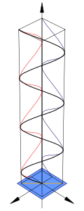
Polarization is a general property of waves that describes the orientation of their oscillations. For transverse waves, like many electromagnetic waves, it describes the orientation of the oscillations in the plane perpendicular to the direction of travel of the wave. The oscillations can be oriented in only one direction (linear polarization), or the oscillation direction can rotate as the wave travels (circular or elliptical). Circularly polarized waves can rotate to the right or to the left with respect to the direction of travel, and which of these two rotations is present in a wave is called the chirality of the wave.
The typical way to consider polarization is to keep track of the orientation of the electric field vector as the electromagnetic wave propagates. The electric field vector of a plane wave can be arbitrarily divided into two perpendicular components labeled x and y (with z indicating the direction of propagation). The shape projected onto the xy plane by the electric field vector is a Lissajous figure describing the "polarization state". The figures above show some examples of the evolution of the electric field vector (blue), with time (the vertical axis), at a particular point in space, along with its x and y components(red/left and green/right), and the path traced by the vector in the plane (purple): the same evolution would occur if the electric field is observed in the opposite direction of propagation at a particular moment while the point evolves in space.
In the figure above, the x and y components of the light wave are in phase. In this case, the ratio of their amplitudes is constant, so the direction of the electric vector (the vector sum of these two components) is constant. Since the tip of the vector traces a single line in the plane, this special case is called linear polarization. The direction of this line depends on the relative amplitudes of the two components.
In the central figure, the two orthogonal components have the same amplitudes and are 90° out of phase. In this case, one component is zero when the other component is at maximum or minimum amplitude. There are two possible phase relationships that satisfy this requirement: the x component can be 90° ahead of the y component , or it can be 90° behind the y component. In this special case, the electric vector traces a circle in the plane, so this polarization is called circular polarization. The direction of rotation in the circle depends on which of the two phase relationships exists and correspond to "right-hand circular polarization" and "left-hand circular polarization".
In all other cases, when the two components do not have the same amplitudes and/or their phase difference is neither zero nor a multiple of 90°, the polarization is called elliptical polarization because the electric vector traces an ellipse in the plane (the ellipse of polarization). This is shown in the figure above to the right. The detailed mathematics of polarization uses the Jones calculus and is characterized by Stokes parameters.
Polarization change
Media that have different refractive indices for different polarization modes are called birefringent. Well-known manifestations of this effect appear in wavesheets/optical retarders (linear modes) and in the Faraday effect/optical activity (circular modes).If the path length in the birefringent medium is sufficient, plane polarized waves will exit the material with a significantly different propagation direction, due to refraction. For example, this is the case for macroscopic calcite crystals, which present the viewer with two offset, orthogonally polarized images of what is seen through them. It was this effect that provided the first discovery of a polarization phenomenon by Rasmus Bartholin in 1669. Furthermore, the change in phase, and thus the change in the state of polarization, is generally frequency dependent, which, in combination with dichroism often results in bright colors and rainbow-like effects. In mineralogy, these properties, known as pleochroism, they are frequently mined for the purpose of identifying minerals using microscopes with polarized light. Furthermore, many plastics that are not normally birefringent become birefringent when subjected to mechanical stress, a phenomenon that is the basis of photoelasticity methods.To rotate the linear polarization of light beams, in addition to the rotating polarizer, there are binoculars that use total internal reflection in a set of prisms designed to obtain efficient collinear transmission.
Media that reduce the amplitude of certain polarization modes are called dichroics, with devices that block almost all radiation in devices known as polarizing filters or simply polarizers. Malus's law, named after Étienne-Louis Malus, says that when a perfect polarizer is placed on a linearly polarized light beam, the intensity, I, of the light passing through it is given by

whereI 0 is the initial intensity, andθ i is the angle between the initial polarization direction of the light and the axis of the polarizer.
A beam of unpolarized light can be thought of as containing a uniform mixture of linear polarizations at all possible angles. Since the average value of 

In practice, some light is lost in the polarizer and the actual transmission of unpolarized light will be somewhat lower, about 38% for Polaroid-type polarizers but considerably higher (>49.9%) for some types of birefringent prisms.
In addition to birefringence and dichroism in large media, polarization effects can also occur at the (reflective) interface between two materials of different refractive index. These effects are treated by the Fresnel equations. Part of the wave is transmitted and part is reflected, and the relationship depends on the angle of incidence and the angle of refraction. In this way, physical optics is related to wave physics through the parameter called the Brewster angle. When light is reflected from a thin film onto a surface, interference between the reflections from the film surfaces can produce polarization in reflected and transmitted light.
Natural light
Most sources of electromagnetic radiation contain a large number of atoms or molecules that emit light. The orientation of the electric fields produced by these emitters may be uncorrelated, in which case the light is said to be "unpolarized." If there is a partial correlation between the emitters, the light is "partially polarized." If the polarization is constant throughout the spectrum of the source, partially polarized light can be described as a superposition of a completely unpolarized and a completely polarized component. Light can be described in terms of its degree of polarization and by the parameters of the polarization ellipse.
When it is reflected by transparent and shiny materials, it is partially or totally polarized, except if the light is normal (perpendicular) to the surface. It was this effect that allowed the mathematician Étienne-Louis Malus to make the measurements that led to the development of the first mathematical models of polarized light. Polarization occurs when light is scattered in the Earth's atmosphere. The scattered light produces the brightness and color of the clear sky. This partial polarization of the scattered light can be exploited by using polarizing filters to darken the sky in certain photographs. Optical polarization is primarily important in chemistry, due to the circular dichroism and optical activity ("circular birefringence") exhibited by optically active chiral molecules.
Modern optics
Modern optics encompasses areas of optical science and engineering that became popular in the 20th century.. These areas of optical science are typically concerned with the electromagnetic or quantum properties of light, but include other topics. An important subfield of modern optics, quantum optics, deals specifically with the quantum mechanical properties of light. Quantum optics is not just theoretical; Some modern devices, such as lasers, have operating principles that quantum mechanics describes. Light detectors, such as photomultipliers and channeltrons, respond to single photons. Electronic image sensors, such as CCDs, exhibit shot noise corresponding to single photon event statistics. LEDs and photoelectric cells cannot be understood without quantum mechanics either. In studying these devices,
Optics research specialty areas include the study of how light interacts with specific materials such as in crystal optics and in metamaterials. Another line of research focuses on the phenomena associated with electromagnetic waves such as optical singularities, non-image optics, non-linear optics, statistical optics and radiometry. Additionally, computer engineering has been interested in integrated optics, machine vision, and optical computers as possible components of the "next generation" of computers.
Today, the pure science of optics is called optical science or optical physics to distinguish it from the applied optical sciences, which are known as optical engineering. Notable subfields of optical engineering include lighting engineering, photonics, and optoelectronics, with practical applications such as optical lens design, optical component manufacturing and testing, and digital image processing. Some of these fields overlap, with blurred boundaries between terms describing the respective disciplines, meaning slightly different things in different parts of the world and in different areas of industry. In recent decades, a professional community of researchers in nonlinear optics has developed, thanks to advances in laser technology.
Láser
A laser is a device that emits light (electromagnetic radiation) through a process called: stimulated emission. The term laser is an acronym for Light Amplification by Stimulated Emission of Radiation. Laser light is generally coherent, meaning that it is emitted in a narrow low beam. divergence or that can be converted into one of these beams with the help of optical components such as lenses. Because the microwave equivalent of lasers, the "maser", was developed first, devices that emit microwave and radio frequencies are generally called "masers".
The first working lasers were introduced on May 16, 1960 by Theodore Harold Maiman at Hughes Research Laboratories. When they were first invented, they were called "a solution looking for a problem". they have become a multimillion-dollar industry, finding utility in thousands of very varied applications. The first application of visible lasers in everyday life for the general population was the supermarket barcode scanner, introduced in 1974. The laserdisc player, introduced in 1978, was the first successful consumer product to include a laser, But the compact disc player was the first truly common laser-equipped device in consumer homes, beginning in 1982.These optical storage devices use a laser diode less than a millimeter wide to scan the surface of the disk for data recovery. Fiber optic communications rely on lasers to transmit large amounts of information at the speed of light. Other common applications for lasers include laser printers and laser pointers. They are also used in medicine in areas such as general surgery, refractive surgery, and laser microdissection; as well as in military applications such as anti-missile systems, electro-optical countermeasures and LIDAR systems. Lasers are also used in holography, 3D engraving, laser displays, and laser hair removal.
In construction, they are used as sheet metal cutting tools; in geodesy and topography, laser rangefinders are used for the precise measurement of distances (as in the extreme case of measuring the distance between the Earth and the Moon, using the mirrors located on the surface of the satellite by different space missions); and in aeronautical navigation they are the basis of ring laser gyroscopes.
Likewise, in some types of nuclear fusion reactors, high-power laser beams are used to reach the high temperatures that this type of reaction requires.
Kapitsa-Dirac effect
The Kapitsa-Dirac effect causes particle beams to diffract as a result of encountering a standing wave of light. Light can be used to manipulate atomic or molecular fragments of matter, exploiting the properties of this phenomenon (see optical tweezer).
Contenido relacionado
GM-NAA I/O
Hittite laws
Donation of Pepin