Graphic projection
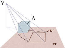
The graphic projection is a word from the Latin proiectio (to do in front),it is a drawing technique used to represent an object on a surface. The graphic projection of an object is considered as the figure obtained on the surface by means of bundles of lines, called projecting lines, which, starting from a point, called Focus, transfer the details of the object to the surface on which they fall.
Elements of a graphic projection
- The viewpoint or projection focus (V{displaystyle V})
- Points to project (BXA{displaystyle BXA})
- Screening of points (A♫{displaystyle A'})
- Projecting demand (VA{displaystyle VA})
- Plane on which projection or projection plan (π π {displaystyle pi }).
General classification
| Projection | Types | Perspective | |
|---|---|---|---|
| Central | Conical perspective with one, two or three escape points. | ||
| Stop it. | Ortogonal | Isometric (three equal angles (120o), equal reduction coef) | |
| Dimetric (two equal angles, two different coefficients) | |||
| Trimetric (three different angles and coefficients) | |||
| Oblique | Perspective Knight, Military Perspective, | ||
Center projection
When all the projecting lines pass through a point, we speak of central projection, conical or perspective, this is the case, for example, of the shadow of an object on a surface when it is illuminated by a lamp (point focus).
It is the one adopted in the conical representation system, or simply conical perspective.
A variant of this representation system is the stereographic projection used for the plane representation of the surface of a sphere, and which is obtained by projecting all the points of the sphere from one of them onto the tangent plane at the point diametrically opposite, or on a plane parallel to it, drawn through the center of the sphere.
Parallel projection
When the projecting lines are parallel –like the previous object illuminated by sunlight–, we speak of parallel projection or cylindrical projection. It is a particular case of central projection, where the focus of the projecting beam would be at an infinite distance.
The dihedral system
This is the case of the dihedral system, in which it is also true that the projecting lines are perpendicular (orthogonal) to the projection plane. In this system, unlike the others, you do not get a volumetric representation of the object in perspective, but "views" as its elevation, plan and profile.
From these views, a three-dimensional representation of the object can be obtained in the axonometric system, whose projecting lines can be both orthogonal and oblique.
The bounded drawing
A variant of the dihedral system, with dimensioning. They are widely used in architecture, engineering, topography, etc.
Contenido relacionado
Plaza de España/Noviciate Station
Titanium carbide
Hohmann transfer orbit


