Galvanometer
A galvanometer is an instrument used to detect and measure electrical current. It is an electromechanical analog transducer that produces a rotational deformation in a needle or pointer in response to current current that flows through its coil. This term has been expanded to include uses of the same device in recording equipment, positioning, and servomechanisms.
It is capable of detecting the presence of small currents in a closed circuit, and can be adapted, through its calibration, to measure their magnitude. Its operating principle (moving coil and fixed magnet) is known as the D'Arsonval mechanism, after the scientist who developed it. This consists of a normally rectangular coil, through which the current to be measured circulates. This coil is suspended within the magnetic field associated with a permanent magnet, along its vertical axis, in such a way that the angle of rotation of said coil is proportional to the current that passes through it. The vast majority of needle indicating instruments used in analog instruments they are based on the explained principle of operation, using a coil suspended within the field associated with a permanent magnet. The suspension methods used vary, which determines the sensitivity of the instrument. Thus, when suspension is achieved by a taut metal tape, full scale deflection can be obtained with only 2 μA, but the instrument is extremely fragile, while the "jewels and pivots" system, similar to that used in watchmaking, it makes it possible to obtain a more robust instrument but less sensitive than the previous one, in which full-scale deflection is typically obtained, with 50 μA.
Origin of the galvanometer
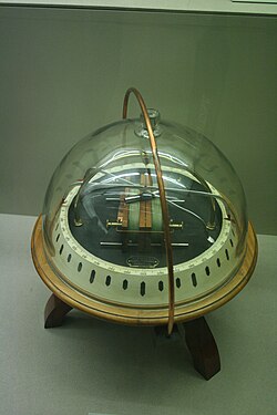
The deflection of magnetic compass needles by current in a wire was first described by Hans Oersted in 1820. The first galvanometers were described by Johann Schweigger at the University of Halle on September 16 of that year. The French physicist André-Marie Ampère also contributed to its development. Early designs increased the effect of the magnetic field due to current by using multiple turns of wire; these instruments were called "multipliers" due to this common design feature. The term "galvanometer", in common use since 1836, derives from the surname of the Italian researcher Luigi Galvani, who discovered that electric current could make a frog's leg move.
Originally, galvanometers relied on the Earth's magnetic field to provide the force to reset the compass needle; these were called "tangent" galvanometers; and had to be oriented, according to the Earth's magnetic field, before use. Later, instruments of the "static" they used opposing magnets, which made them independent of the Earth's magnetic field and could operate in any orientation. The most sensitive form, the Thompson or mirror galvanometer, was invented by William Thomson (Lord Kelvin). Instead of having a needle, he used tiny magnets attached to a small lightweight mirror, suspended by a thread. It was based on the deflection of a highly magnified beam of light due to small currents. Alternatively, the deflection of the suspended magnets could be observed directly through a microscope.
The ability to quantitatively measure voltage and current in galvanometers allowed physicist Georg Ohm to formulate Ohm's Law, which states that the voltage across a conductor is directly proportional to the current through it.
The first moving magnet galvanometer had the disadvantage of being affected by any magnet or iron object placed nearby, and the deflection of its needle was not proportionally linear to the current. In 1882, Jacques-Arsène d'Arsonval developed a device with a permanent static magnet and a moving coil of wire, suspended by coil springs. The concentrated magnetic field and delicate suspension made this a sensitive instrument that could be mounted in any position. In 1888, Edward Weston developed a commercial form of this instrument, which became a standard component in electrical equipment. This design is almost universally used in moving vane gauges today.
Galvanometer components
All types of galvanometers basically contain all of these elements:
- Permanent magnet or temporary magnet
- Mobile coil
- Indicator needle
- Scale in units according to reading types
- Pivotes
- Cojinetes
- Resorts
- Retention bolts
- Zero adjustment screw
- Removement mechanism
Types of galvanometers
Depending on the internal mechanism, galvanometers can be moving magnet or moving frame.
Moving Magnet
In a moving magnet galvanometer, the indicator needle is associated with a magnet that is located inside a coil through which the current to be measured circulates and that creates a magnetic field that, depending on the direction of it produces an attraction or repulsion of the magnet proportional to the intensity of said current.
Mobile frame
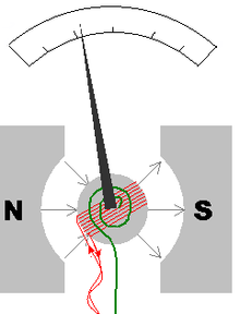
In the moving frame or moving coil galvanometer, the effect is similar, differing only in that in this case the indicator needle is associated with a small coil, through which the current to be measured circulates and which is found within the of the magnetic field produced by a fixed magnet.
The diagram on the right shows a moving frame galvanometer in which, in red, the moving coil or frame can be seen and in green the spring that causes the indicator needle to return to the rest position once it is turned off. current flow ceases.
In the case of thermal galvanometers, what is revealed is the elongation produced when heating, by the Joule Effect, the passage of a current, a very thin wire wound around a cylinder attached to the indicator needle. Logically, the greater or lesser elongation is proportional to the intensity of the current.
Contenido relacionado
Density
Year
Data link layer


