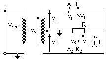
Full wave rectifier
A full-wave rectifier is a circuit used to convert an input alternating current signal (Vi) into an output pulsating current signal (Vo). Unlike the half-wave rectifier, in this case, the negative part of the signal becomes positive or the positive part of the signal will become negative, depending on whether a positive or negative DC signal is needed.
There are two alternatives, either using two diodes or using four (Graetz bridge).
Rectifier with two diodes
In the circuit of the figure, both diodes cannot be simultaneously in direct or inverse, since the potential differences to which they are subjected are of opposite sign; therefore one will be inversely polarized and the other directly. The input voltage (Vi) is, in this case, the average of the secondary voltage of the transformer.
Positive input voltage
Diode 1 is forward biased (conducts), while 2 is reverse biased (does not conduct). The output voltage is equal to the input voltage. Note:diodes in forward position conduct high currents, in reverse position high voltages.
Negative input voltage
Diode 2 is forward biased (conducts), while diode 1 is reverse biased (does not conduct). The output voltage is equal to the input voltage but with the opposite sign. Diode 1 must withstand the maximum secondary voltage in reverse.
08
Graetz Bridge or Double Wave Rectifier Bridge
In this case, four diodes are used with the arrangement of the figure. As before, only two conduction states are possible, either diodes 1 and 3 are in direct and conduct (positive voltage) or on the contrary, diodes 2 and 4 are in direct and conduct (negative voltage).).
Unlike the previous case, now the maximum output voltage is that of the secondary of the transformer (double that of the previous case), the same that the diodes have to withstand in reverse, as in the rectifier with two diodes. This is the configuration usually used to obtain a continuous wave that is rectified
Rectified voltage
- Vo (continuous output voltage) = Vi (alternative input pressure) = Vs/2 in the rectifier with diodes.
- Vo = Vi = Vs in the rectifier with bridge of Graetz.
If we consider the typical voltage drop of silicon diodes in conduction, approximately 0.7V; we will have that for the case of the double wave rectifier the Vo = |Vi| - 1.4V.
Contenido relacionado
Zepto
Warchalking
Porcelain


