
Electric capacitor
In electricity and electronics, a capacitor or capacitor is a passive device capable of storing energy by sustaining an electric field. It consists of by a pair of conductive surfaces, generally in the form of sheets or "plates", in a situation of total influence (that is, all electric field lines that start from one go to the other) separated by a dielectric material or by vacuum. The plates, subjected to a potential difference, acquire a certain electrical charge, positive in one of them and negative in the other, the total charge variation being zero.
Although from the physical point of view a capacitor does not store charge or electrical current, but simply latent mechanical energy, when introduced into a circuit, it behaves in practice as an element "capable" of storing the electrical energy it receives during the charging period, the same energy that it releases later during the discharge period.
History


In October 1745, Ewald Georg von Kleist, from Pomerania (Germany), observed that electrical charge could be stored by connecting an electrostatic generator to a volume of water inside a jug, flask or bottle by means of a cable of glass. Von Kleist's hand and the water acted as conductors, and the flask as a dielectric, that is, an insulator (although the details of the mechanism were incorrectly identified at the time). Von Kleist was jolted by touching the wire with a powerful spark, much more painful than that obtained from an electrostatic generator, so he correctly deduced that electrical charge was stored in that device.
The following year, the Dutch physicist Pieter van Musschenbroek invented a similar condenser that was called a Leyden jar (after the Leiden University where he worked). He was also impressed by the force of the discharge that this device provided, so that he came to write that "he would not suffer a second discharge throughout the kingdom of France".

Daniel Gralath was the first to combine several Leyden jars in parallel to form a "battery" to increase charge storage capacity. Likewise, Benjamin Franklin investigated the Leyden jar and concluded in 1749 that the charge was stored not precisely in the water, as others had assumed, but on the edge of the glass. He also coined the term "battery" (indicating the increase in power by means of a row of similar units, as in artillery batteries) which was later applied to groups of electrochemical cells. Thanks to Franklin's discovery, later Leyden jars were made by lining the inside and outside of the jars with metal foil, leaving a gap at the mouth to prevent arcing between the foils. The first unit of capacity was the "jar", equivalent to about 1.11 nanofarads. The inductance or measure of the opposition to a change in current of an inductor that stores energy in the presence of a magnetic field began to be studied.
Leyden jars or more powerful devices (using flat glass plates alternated with metal foil conductors) were used until about 1900, when the invention of wireless telegraphy created a new demand for capacitors (term first used by Alessandro Volta in 1782) such as sheets of flexible dielectric (ie, insulating) material. A capacitor (generally indicated with C) was generally made up of a pair of conductors (or plates) separated by an insulator (dielectric). The charge was stored on the surface of the plates of conductive material, on the edge in contact with the dielectric or insulator.
Since the beginning of the study of electricity, non-conductive materials such as glass, porcelain, paper and mica were used for capacitors as insulators or dielectrics. In Guillermo Marconi's early years, porcelain capacitors were used for wireless transmitting devices, while small mica capacitors were used for reception in resonant circuits. The latter, mica capacitors, were invented in 1909 by William Dubilier. Before World War II, mica was the most common dielectric for capacitors in the United States.
Charles Pollak (born Karol Pollak) was the inventor of the first electrolytic capacitors. In 1896 he was granted US Patent No. 672,913 for an "Electrical Liquid Capacitor with Aluminum Electrodes". Solid electrolyte tantalum capacitors were invented in the 1950s by Bell Laboratories as more reliable, miniaturized, low-voltage backup capacitors to complement the new invention of the transistor.
With the development of plastic materials by organic chemists during World War II, the industry began to replace the paper capacitor with thin polymer films. A very early development of film capacitors is described in British patent 587,953 from 1944. Last, but certainly not least, is the electrical double layer capacitor, or supercapacitor.
Operation
The charge stored in one of the plates is proportional to the potential difference between this plate and the other, being the constant of proportionality the so-called capacity or capacitance. In the International System of units it is measured in Farads (F), being 1 farad the capacity of a capacitor in which, subjected to a potential difference of 1 volt, they acquire an electric charge of 1 coulomb.
The capacitance of 1 farad is much larger than most capacitors, so in practice the capacitance is usually stated in micro- µF = 10-6, nano- nF = 10-9 or pico- pF = 10-12 -farads. Capacitors obtained from supercapacitors (EDLC) are the exception. They are made of activated carbon to achieve a large relative area and have molecular spacing between the 'plates'. Thus capacities of the order of hundreds or thousands of farads are achieved. One of these capacitors is incorporated into Seiko's Kinetic watch, with a capacity of 1/3 of a farad, making a battery unnecessary. It is also being used in electric car prototypes.
The value of the capacity of a capacitor is defined by the following formula:
C=Q1V1− − V2=Q2V2− − V1{displaystyle C={frac {Q_{1}}{V_{1}-V_{2}}}}}}{frac {Q_{2}}{V_{2}-V_{1}}}}}}}}}}}

where:
- C{displaystyle C}: Training or capacity.
- Q1{displaystyle Q_{1}}: Electric charge stored in plate 1.
- V1− − V2{displaystyle V_{1}-V_{2}}}}: Potential difference between plate 1 and 2.


Note that in the definition of capacity it does not matter whether the charge of the positive or the negative plate is considered, since
Q2=C(V2− − V1)=− − C(V1− − V2)=− − Q1{displaystyle Q_{2}=C(V_{2}-V_{1})=-C(V_{1}-V_{2})=-Q_{1},}

although by convention the charge of the plate is usually considered positive.
Regarding the constructive aspect, both the shape of the plates or armor and the nature of the dielectric material are highly variable. There are capacitors made up of plates, usually aluminum, separated by air, ceramic materials, mica, polyester, paper, or by a layer of aluminum oxide obtained through electrolysis.
Stored energy, formulas and terms
When the potential difference between its terminals increases, the capacitor stores electrical load due to the presence of an electric field inside it; when it decreases, the capacitor returns that load to the circuit. Mathematically you can get the energy E{displaystyle {mathcal {E}}}, stored by a capacity capacitor C{displaystyle C}which is connected to a potential difference V1− − V2{displaystyle V_{1}-V_{2}}}}It is given by:

Formula for any values of initial stress and final stress:
E=∫ ∫ q1q2Vdq=∫ ∫ q1q2QCdq=12C(V22− − V12){displaystyle {mathcal {E}}=int _{q_{1}}}{q_{2}}}}}Vmathrm {d} q=int _{q_{1}}}{q_{2}{2}{frac}{Q}{C}{C}{mathrm {d} q={frac {1}{1{1⁄2}{1⁄2}{1⁄2}}{1⁄2}{1⁄2}}{1⁄2}{1⁄2}{1⁄2}}}{1⁄2}}{1⁄2}}{1⁄2}}{1⁄2}}{1⁄2}}{1⁄2}}{1⁄2}{1⁄2}}}}}{1⁄2}}{1⁄2}{1⁄2}{1⁄2}}}}}{1⁄2}}{1⁄2}{

Where
- q1{displaystyle q_{1}} It's the initial load.
- q2{displaystyle q_{2}} It's the final load.
- V1{displaystyle V_{1}} It's the initial tension.
- V2{displaystyle V_{2}} It's the final tension.


This fact is used to manufacture memories, in which the capacity that appears between the gate and the channel of the MOS transistors is used to save components.
Upload and download
When connecting a capacitor in series with a resistor to an electrical voltage source (or commonly, a power source), current begins to flow through both. The capacitor accumulates charge between its plates. When the capacitor is fully charged, no current flows through the circuit. If the source is removed and the capacitor and resistor are placed in series, charges begin to flow from one plate of the capacitor to the other through the resistor, until the charge or energy stored in the capacitor is zero. In this case, the current will flow in the opposite direction to the one it flowed while the capacitor was charging.
- Charge
- V(t)=Vf(1− − e− − tRC){displaystyle V(t)=V_{f}(1-e^{-{frac {t{RC}}}}}})}
- I(t)=VfR(e− − tRC){displaystyle I(t)={frac {V_{f}}{R}}}(e^{-{frac {t}{RC}}}}})}
- V(t)=Vf(1− − e− − tRC){displaystyle V(t)=V_{f}(1-e^{-{frac {t{RC}}}}}})}


- Download
- V(t)=Vie− − tRC{displaystyle V(t)=V_{i},e^{-{frac {t{RC}}}}}}}}
- I(t)=− − ViR(e− − tRC){displaystyle I(t)=-{frac {V_{i}}{R}}}(e^{-{frac {t}{RC}}}}}}


Where:
- V(t) is the tension in the capacitor.
- Vi is the voltage or difference of initial electrical potential (t=0) between the capacitor plates.
- Vf is the voltage or difference of final electric potential (to stationary regimen t ≥ 4RC) between the capacitor plates.
- I(t) the current intensity that circulates through the circuit.
- RC is the capacity of the capacitor in faradios multiplied by the resistance of the circuit in ohms, called constant time.
In alternating current
In CA, an ideal capacitor offers a resistance to the passage of electricity that receives the name capacitive reactance, XC, whose value is given by the reverse of the pulsation product (ω ω =2π π f{displaystyle quad omega =2pi f}) for capacity, C:

XC=1ω ω C{displaystyle X_{C}={1 over omega C}}

If the pulsation is expressed in radians per second (rad/s) and the capacitance in farads (F), the reactance will result in ohms.
According to the law of Ohm, the alternating current that circulates through the capacitor will advance 90° (π π /2{displaystyle pi /2}) regarding the voltage applied.

Capacitor Associations


Capacitors can be associated in series, parallel or mixed. In these cases, the equivalent capability turns out to be for the serial association:
| 1CAB=1C1+1C2+...+1Cn=␡ ␡ k=1n1Ck{displaystyle {1 over C_{AB}}={1 over C_{1}}}}+{1 over C_{2}+...+{1 over C_{n}}}={sum _{k=1}{n}{1 over C_{k}}}}}}}}} |

y for the parallel association:
| CAB=C1+C2+...+Cn=␡ ␡ k=1nCk{displaystyle C_{AB}=C_{1}+C_{2}+C_{n}=}sum _{k=1}{n}C_{k}}} |

That is, the sum of all the capacities of the capacitors connected in parallel.
It is easy to demonstrate these two expressions, for the first one you only have to bear in mind that the load stored on the plates is the same in both capacitors (you have to induce the same amount of load between the plates and therefore changes the difference of potential to maintain the capacitance of each one), and on the other hand in the association in "parallel", you have to the difference of potential between both plates has to be the same (be connected to). As this is found in the numerator (C=Q/V{displaystyle C=Q/V}) the sum of abilities will simply be the algebraic sum.

It's also worth remembering that calculating parallel equivalent capacitance is similar to calculating the resistance of two devices in series, and series capacitance or capacitance is calculated similarly to parallel resistance.
Variable Capacitors
A variable capacitor is one in which the value of its capacity can be changed. In the case of a flat capacitor, the capacity can be expressed by the following equation:
C=ε ε 0ε ε rAd{displaystyle C=epsilon _{0}epsilon _{r}{frac {A}{d}}}}}

where:
- ε ε 0{displaystyle epsilon} is the allowivity of vacuum ≈ 8,854187817... × 10−12 F·m−1;
- ε ε r{displaystyle epsilon} is the relative dielectric constant or permitivity of the dielectric material between the plates;
- A is the effective area of the plates;
- and d is the distance between the plates or thickness of the dielectric.


To have a variable condenser, at least one of the last three expressions must change its value. In this way, it is possible to have a capacitor in which one of the plates is mobile, therefore d varies and the capacity will depend on this displacement, which could be used, for example, as a sensor of displacement.
Another type of variable capacitor occurs in Varicap diodes.
Ideal and real behaviors

The ideal capacitor (figure 1) can be defined from the following differential equation:
i(t)=Cdu(t)dt{displaystyle i(t)=C{du(t) over dt};}

where C is the capacitance, u(t) is the potential difference function applied to its terminals and i(t) is the current circulating resultant.
Behavior in direct current
A real DC capacitor behaves practically like an ideal one, that is, like an open circuit. This is so in a permanent regime since in a transient regime, that is, when connecting or disconnecting a circuit with a capacitor, transient electrical phenomena occur that affect the potential difference in its terminals (see RL and RC series circuits).
Alternating current behavior

When connecting a sinusoidal AC v(t) to a capacitor, a current i(t) will flow, also sinusoidal, which will charge it, causing a drop in its terminals of tension, -vc(t), whose absolute value can be shown to be equal to that of v(t). All of the above, once the stationary regime has been reached. When saying that a current "circulates" through the capacitor, it must be pointed out that, in reality, said current never passes through its dielectric. What happens is that the capacitor charges and discharges at the rate of the frequency of v(t), so current flows externally between its armatures. This refers to the conduction current but, inside the dielectric we can talk about the displacement current.

The physical phenomenon of the behavior of the capacitor in AC can be observed in figure 2. Between 0º and 90º i(t) decreases from its maximum positive value as its voltage increases load vc(t), becoming zero when it reaches the maximum negative value at 90º, since the sum of stresses is zero (vc(t)+ v(t) = 0) at that time. Between 90º and 180º v(t) decreases, and the capacitor begins to discharge, thus decreasing vc( t). At 180º the capacitor is completely discharged, reaching i(t) its maximum negative value. From 180º to 360º the reasoning is similar to the previous one.
From all of the above, it can be deduced that the current is 90º ahead of the applied voltage. Considering, therefore, a capacitor C, like the one in figure 1, to which an alternating voltage of value is applied:
u(t)=V0⋅ ⋅ without (ω ω t+β β ){displaystyle u(t)=V_{0}cdot sin(omega t+beta)}

According to the law of Ohm will circulate an alternating current, advanced 90o (π π /2{displaystyle pi /2}) regarding the applied voltage (Figure 4), of value:
i(t)=I0⋅ ⋅ without (ω ω t+β β +90 ){displaystyle i(t)=I_{0}cdot sin(omega t+beta +90^{circ })}}

where I0=V0jXC{displaystyle I_{0}={V_{0} over jX_{C}}}}. If the effective value of the current obtained in polar form is represented:

I→ → =I/β β +90 _ _ {displaystyle {vec {I}}=I_{/!!{underline {beta +90^{circ}}}}}}}


And operating mathematically:
- I→ → =(VXC)/β β +90 _ _ =V/β β _ _ XC/− − 90 _ _ {displaystyle {vec {I}}=left({V over X_{C}}right)_{/!!{underline {beta +90^{circ}}}{V}{V_{/!!{underline {beta }}}{X_{c}{c}{x}{c}{c}{c}{c}{c}{c}{

Therefore, in AC circuits, an ideal capacitor can be assimilated to a complex magnitude with no real part and negative imaginary part:
XC→ → =0− − jXC=XC/− − 90 _ _ {displaystyle {vec {X_{C}}}=0-jX_{C}={X_{C}}}}_{/!{underline { -90^{circ}}}}}}}}}}}
In the real capacitor, it will be necessary to take into account the loss resistance of its dielectric, RC, which may be its equivalent circuit, or model, the one that appears in figure 4a) or 4b) depending on the type of condenser and the frequency at which it works, although for more precise analysis more complex models can be used than the previous ones.
Types of dielectric used in capacitors


- Air Condensers. These are capacitors, usually of parallel plates, with dielectric air and encapsulated in glass. Since relative electric permitivity is the unit, it only allows very small capacity values. It was used on radio and radar, as they lack loss and polarization in the dielectric, working well at high frequencies.
- Condensadores de mica. The mica has several properties that make it suitable for dielectric capacitors: low losses, exfoliation in fine foils, supports high temperatures and is not degraded by oxidation or moisture. On a face of the mica foil is deposited aluminum, forming a armor. Several of these sheets are stacked, welding the ends alternatively to each of the terminals. These capacitors work well in high frequencies and support high tensions, but are expensive and gradually replaced by other types.
- Paper condemners. The dielectric paper is paraffin, skeleton or subjected to any other treatment that reduces its higroscopia and increases isolation. Two sheets of paper, one of aluminum, two of paper and another of aluminum are stacked and rolled in spiral. The aluminum ribbons constitute the two armors, which connect to terminal sendos. Two paper ribbons are used to avoid the pores they can present.
- Condensadores autorregenerables. Paper capacitors have applications in industrial environments. The self-regenerable capacitors are paper capacitors, but the armor is made by depositing aluminum on the paper. In the face of an overload situation that exceeds the dielectric rigidity of the dielectric, the paper breaks at some point, producing a short circuit between the armors, but this short causes a high current density by the armor in the area of the breakage. This current melts the thin layer of aluminum that surrounds the short circuit, restoring the isolation between the armors.
- Electrolytic Condensers. It is a type of capacitor that uses an electrolyte, like its first armor, which acts as a cathode. With appropriate tension, the electrolyte deposits an insulating layer (which is generally a very thin layer of aluminum oxide) on the second armor or bucket (anod), thus achieving very high capacities. They are inadequate to operate with alternating current. Reverse polarization destroys the oxide, producing a short circuit between the electrolyte and the cube, increasing the temperature, and therefore burns or stalls the capacitor accordingly. There are several types, according to their second armor and electrolyte used:
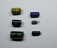 Electrolytic enclosures of different sizes
- Aluminum Condensers. He's the normal guy. The cube is made of aluminum and the electrolyte a dissolution of rhetoric acid. It works well at low frequencies, but it has large losses at medium and high frequencies. It is used in power supply and audio equipment. Very used in switched power sources.
- Tantalo Condensers (tantalos). It is another electrolytic capacitor, but employs tantalin instead of aluminum. Get low loss currents, much lower than in aluminium capacitors. They usually have better capacity/volume ratio.
- Bipolar Condensers (for alternating current). They are formed by two inverse series electrolytic capacitors, used in case the current can be reversed. They are useless for high frequencies.
- Condensadores de poliéster or Mylar. It consists of thin sheets of polyester on which aluminum is deposited, which forms the armors. These sheets are stacked and connected to the ends. Similarly, polycarbonate and polypropylene capacitors are also found.
- Condensadores de poliestireno also commonly known as Styroflex (signed from Siemens). Another type of plastic capacitors, widely used in radio, for having inverse temperature coefficient to the tuning coils, thus achieving stability in the resonating circuits.
- Ceramic Condensers. It uses ceramics of various types to form the dielectric. There are different types formed by a single sheet of dielectric, but they are also formed by stacked sheets. Depending on the type, they work at different frequencies, reaching the microwave.
 Ceramic and polyester cups of different sizes
 - Synchronous convictions. It is a synchronous motor that behaves like a capacitor.
- Variable dielectric. This type of capacitor has a mobile armor that revolves around a shaft, allowing it to be inserted more or less into the other. The armor profile is usually such that the capacity variation is proportional to the angle logarithm that rotates the shaft.
- Adjustment Condensers. These are special types of variable capacitors. The armors are semicircular, and one of them can revolve around the center, thus varying the capacity. Another type is based on approaching the armors, using a screw that tightens them.


Uses
Capacitors are often used for:
- Batteries, for their quality of storing energy.
- Memories, by the same quality.
- Filters.
- Power supplies.
- Adaptation of impedances, making them resonate to a given frequency with other components.
- Demodular AM, along with a diode.
- Oscillators of all types.
- The flash of the cameras.
- Fluorescent tubes.
- Power factor compensation.
- Starting-phase single-phase engines.
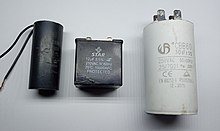 Boot caps for single-phase engines
 - Keep current in the circuit and avoid voltage drops.

Contenido relacionado
MediaWiki:Ipblocklist
<h2>By range of instruments</h2>
980