Bogie
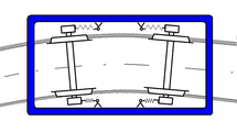
The bogie, bogie or boje is a set of two (or sometimes three or more, depending on the model) pairs of wheels, mounted on two nearby axes, parallel and solidary to each other, which are used at both ends of long vehicles intended to circulate on rails. The vehicle body is supported by means of a vertical axis through a pivot in each of the bogies; thanks to which it can describe very closed curves.
You can find tractor bogies and carrier or towed bogies, the latter without traction force. In short, it is the rolling structure on which current wagons, railway cars and locomotives rest, which do not use simple axles. A bogie consists of a platform and a series of axles with the corresponding wheels, and is attached to the vehicle by means of a vertical pivot that allows it to turn to both sides when cornering.
The wagons, cars and locomotives that carry bogies generally have two units, one at each end. An exception is Renfe's 251 series, which has three bogies.
High-speed trains with short cars have bogies located at opposite ends of two adjoining cars, in an arrangement called shared bogie.
Description

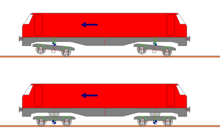
The essential function of the bogies is to facilitate the registration of the rolling stock in the curves. In fact, the bogies of the vehicle can pivot independently of each other, which allows the track to be laid out with smaller radii of curvature and adopt longer wheelbases (whether motors or carriers).
The vehicle's cargo typically rests on the bogie, supported by a vertical cylindrical ball joint (located on the bogie) and a pivot (attached to the wagon frame) secured by a bolt. In current vehicles, the bogie can slide freely under the body of the wagon, which facilitates the bogie assembly and disassembly operations; in this case, one speaks of a "fictitious pivot" as in the SNCF trains type "Corail".
In steam locomotives, for example, bogies (generally front, but also rear) were introduced to better distribute the weight of the locomotive without multiplying the number of driving axles, and therefore, avoiding the problem of having to adopt too big a rigid battle.
These are mechanical elements whose design prioritizes safety and reliability, designed to withstand high loads and speeds. Consequently, its construction is especially robust, and given its large size (the distance between the two axes of the cart is usually more than 2 meters) its own weight can range between 4 and 6 tons.
History
Longer and longer locomotives entering a tight radius curve quickly became a problem for rail teams. There were two types of solutions:
- Use articulated single axes, such as those of the Arnoux system or the Bissel type
- Use small two-axis reels each, located at each end of the vehicle
In fact, this last solution, commonly adopted in American rolling stock, is the one that would end up prevailing.
The bogie concept was introduced to the railroad field on December 30, 1812, under patent #3632 filed by brothers William Chapman and Edward Walton Chapman. Bogies spread rapidly throughout the United States from from 1830, because the rolling stock had to travel on roads that were often in poor condition. In France, the bogie appeared for the first time in 1890, as part of the towed material.
In steam locomotives, the bissel axle and then the bogie gradually appeared as the locomotives became more powerful, and therefore longer and heavier. These axles were not tractors, and were intended to distribute the load of the locomotive over the track. The bogie-Bissell was also used, in which one axle was linked to the first driving axle. The best known of these systems was the Zara type. Another special case was the use of a Bissell double axle at the rear of the engine, as on the Hudson locomotives.
Numerical nomenclature for steam locomotives is a series of three digits indicating the number of "front tag axles", then the number of driving axles, then the number of "axles rear carriers". For example, the famous Pacific 231 configuration includes the 2 tag axles of the front bogie; 3 drive axles; and 1 Bissel axis. For the drive axles of electric locomotives and diesel locomotives, an equivalent nomenclature is used, in which letters are used.
In its first hundred years of development, the design of bogies for towed material gave rise to four main groups:
- (1885-1930) Bogie Wagons-Lits
- (1908-1970) Bogie Pensilvania
- (1950-1966) Bogie Milwaukee
- (1967-1990) Bogie Y28 and its derivatives
Its constructive characteristics and its reliability were gradually improved, reducing its weight, introducing more effective braking systems and adopting increasingly efficient suspension systems, which made it possible to increase the design speeds and comfort of passenger cars. In models for speeds of up to 200 km/h and higher, the use of anti-tie damping devices has become common, which reduce the transverse sinusoidal oscillatory displacement of the axes.
It was only from 1950, with the development of electric locomotives and diesel locomotives, that driving bogies became widespread. "Total traction" locomotives became common, with some exceptions such as the A1A A1A type, where between each pair of motor axles there was a supporting axle to distribute the load.
Structure
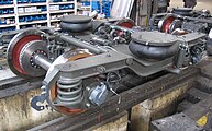
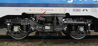
Bogies consist of a frame to which all of its other parts, such as wheelsets, suspension, and shock absorbers, are attached. In the case of powered bogies, the motors and gears are usually also housed in the bogie.
| Parts of a bogie of a passenger car | |
|
|
Frame
The frame of the bogie generally consists of two longitudinal beams located on the bearings of the axles, and one or more cross members. Crossmembers located in front of or behind the axles are called "header brackets". Designs without rigid overhead supports are called H-frames, and are characterized by the fact that the ends of the H that sit on top of the shaft bearings can flex relative to each other. Frames without a cross member between the axles are sometimes called O-frames. Today, the frame is mainly a welded steel structure, less often it also contains castings or is cast as a whole. In the past, they were also built using sheets riveted with rivets.
Shaft bearing
Axle bearings are used to support the wheelset. They can be arranged to be rigid or movable in the longitudinal direction with respect to the bogie frame. Movable bearings allow adequate radial adjustment of the axles in curves.
They are usually found at the ends of each axle, outside the wheels, where they are easily accessible for maintenance, although there are designs (much less frequent) in which they are located between the wheels (internal bogie). In the case of externally mounted bogies, the axle bearings are generally supported by brackets to which the primary springs and their dampers are attached.
Most European freight wagon bogies have a wheelbase of around 1.8 to 2.3 meters. High-speed vehicles are designed with wheelbase supports up to 3 meters, to achieve smoother running.
Suspension
For a better ride comfort and to be able to absorb the torsion of the track introduced by the camber, the bogies are provided with a suspension system. Thus, the two axles bear against the bogie (primary suspension) and the frame of the bogie bears against the body of the car (secondary suspension). In the case of freight car bogies, usually only one of the mentioned spring levels is included; but the bogies of passenger cars and locomotives generally have both levels of suspension.
Primary Suspension
The axle bearing brackets are connected to the bogie frame via primary springs. In the past, leaf springs were used, now replaced by coil springs or springs with elastomeric rings. The axle bearings are guided by articulated bars to the frame.
Primary suspension coil springs are generally arranged vertically, except on Wegmann bogies or bogies with axle control.
Secondary Suspension
Secondary suspension for passenger cars generally consists of coil springs or air springs, locomotive bogies use coil springs, and freight cars in Europe generally do not have secondary suspension.
In the past, secondary suspension was mostly done with leaf springs. Secondary suspensions with Flexicoil suspension or air springs can also take over the lateral guidance of the bogie and its rotation relative to the vehicle body, so that the cradle with the side sliders is not necessary. If longitudinal forces are transmitted by tie rods and push rods, particularly in the case of drive bogies, the pivot pin or swivel bushing is also unnecessary.
Crib
In bogies with secondary suspension, the cradle is a cross member connected to the bogie frame by springs, on which the pivot is located. Unlike cradleless designs, cradled bogies can achieve larger angles of rotation compared to the vehicle body, which is particularly important in the case of tight radii curves.
Pivot
The trunnion, also called a turntable, connects the bogie to the body of the vehicle, and generally also transfers the longitudinal forces between the two. The bogie moves around the vertical axis formed by the pivot. Most of the time, it is supported in the cradle by side sliding plates, which do not absorb longitudinal or transverse forces. Instead of the pivot, mechanisms with lemniscatic linkage can also be used.
Vibration damper
Vibration dampers prevent excessive movement between the bogie and the vehicle body. Leaf springs generally do not require special vibration dampers, since their movement is already damped by friction between the spring leaves.
Typically, additional components are needed for vibration damping of coil or pneumatic springs. In the case of freight cars, simple friction dampers are used; on vehicles for higher speeds, the primary suspension must be designed very stiff and rotation of the bogie frame relative to the vehicle body must be avoided with yaw dampers in order to achieve limiting bow motion to the lowest possible frequency.
Anti-Tip Bracket
In vehicles with a high center of gravity, an anti-tip device can also be installed, which prevents the vehicle body from making excessive rotational movements around the longitudinal axis. The rollover bracket generally consists of a torsion bar that is mounted to the bogie in the transverse direction of the vehicle and that is connected to the body of the vehicle through links on both sides. Alternatively, the torsion bar can also be mounted on the vehicle body and connected to the bogie via a bar.
Drive team
Bogies with driven axles are called "powered bogies". In vehicles with electric traction, the motors are usually also housed in the bogie, as are the gearboxes when power is transmitted via a cardan shaft. There are also vehicles with an internal combustion engine housed in a bogie, which also includes the transmission unit.
Due to their different tasks, motor bogies are designed differently than non-drive bogies. In addition to their supporting and guiding function, motorized bogies also have the task of transmitting traction power. This means that a series of anchors and linkages must be provided to distribute wheel set loads evenly between the axles.
Accession with electric motors:
|
The bogie frame must also be equipped with torsion bars, through which the driving forces are transmitted to the frame. For standardization purposes, wagon bogies are often built in the same way.
Radial wheel set control
In most bogies, the wheel set bearings are fixed longitudinally to the frame, so that the two axles always run exactly parallel to each other. Under these conditions, depending on the wheelbase, the wheel sets of these bogies can still effectively enter relatively tight curves.
In some types of bogies, the wheel set bearings are elastically supported in the longitudinal direction, so that the axles can be adjusted radially with respect to the center of the curve being traveled. The conicity of the wheels allows some radial adjustment, but this effect can be canceled when driving slowly, with disturbances of the traction transmission or other disturbing effects. If the shaft bearings are diagonally connected to each other with tie rods, it is guaranteed that the shafts are always placed in converging directions. In addition, the radial adjustment of the wheelsets can also be achieved by means of a forced steering mechanism through the angle of rotation of the bogie frame in relation to the vehicle body, as for example in the Liechty bogie. Radial configuration can also be achieved using computer based actuators.
Functions
In addition to its role as a link between the axles and the boxes of the rolling stock elements, the bogie performs braking, suspension of the entire train and, sometimes, traction missions. Therefore, there are two main types of bogies:
- The tractor bogies, equipped with a motor in the case of direct traction or with gears in the case of indirect traction.
- The bearing or tow bogies (no motor), usually dedicated to ensuring the distribution of the loads, and the guided and braking of the mobile material.
Each vehicle (locomotive, car, or wagon) has its own bogies (usually two); or they are located between every two elements (Jacobs bogies, used in articulated trains, particularly in the TGV and in the different Talgo models).
Each bogie generally has at least two axles, except in special cases such as:
- The Spanish expression "Talgo", whose cars are based on intermediate bogies with an axis by bogie.
- The Turbo Train UAC, a fast train that was put into service in North America in 1968 with one-axis shared bogies.
- Vagons to transport heavy loads, where you can count several axes per bogie.
- Some motors, such as the Bugatti Motor with four axes per bogie; and the Michelin, where the number of axes is variable.
- The trains that cover the three routes of the Eastern region of France and the two prototypes of the Swiss Federal Railways. In these two cases, the increase in axes is the result of replacing steel wheels with tyres.
Usually the floor of the vehicle is above the bogies. However, this rule does not apply to certain types of railway equipment, such as double-decker trains or wagons that are lowered to accommodate bulky loads, where the floor or loading surface is placed at a lower elevation between the bogies. There are also trams with ultra low floors without bogies.
Special Types
Multi-axle bogies
Most bogies used today are bi-axle, but there are also bogies with three or more axles.
Three-axle bogies are mainly used for locomotives and wagons designed for heavy loads. In the case of passenger cars, they were mainly used for sleeping cars, restaurant cars and cars with special rooms, in order not to exceed the permitted axle load on the routes traveled. In the case of triaxial bogies, the central axis can generally be moved transversely to avoid registration problems.
For particularly heavy loads, bogies with up to seven sets of wheels have also been built, wagons with several fully equipped axles on which a loading bridge is placed. The suspensions of the adjacent wheelsets are connected to each other with equalizing bars so that they are loaded as evenly as possible.
Single axle bogies
In some cases, the individual axles are also arranged on a frame that can rotate relative to the body of the vehicle. To avoid misconfigurations, single-axle bogies have primarily been built with a mechanical linkage, which is controlled by the vehicle body or by an adjacent running gear. In three-axle trams, a central axle controlled the deflection of the two single-axle bogies, mechanically orienting them.
Bogies with free wheels
The bogies can also be equipped with systems that allow the wheels of the same axle to rotate independently of each other. However, the running behavior of such single wheel bogies is very different from that of conventional set of wheels bogies. Due to the lack of connection between the two wheels of each axle, no transverse sliding forces are generated, so there is no loop movement in a straight line. However, the self-centering effect of the curve is also lost. Even small deviations in the position of the axles mean that a wheel runs permanently with the flange in contact with the head of the rail. Unless complex countermeasures are taken, freewheel assemblies involve considerable rail side wear.
Jakob bogies
Shared bogies were specially developed to achieve longer and tightly connected trains. With this system, the two bodies of two different wagons are supported together on the same bogie arranged between them. The main advantage is to reduce the number of bogies, but at the cost of not being able to split the trains as easily as with conventional wagons, and increasing the axle load for a given wagon length. This is often offset by the fact that they are designed for shorter cars than those fitted with conventional bogies.
Cleminson System
The Cleminson system is not a true bogie, but it serves a similar purpose. It was based on an 1883 patent by James Cleminson, and was once popular on narrow gauge rolling stock, such as on the Isle of Man Railway. The vehicle would have three axles and the outer two could pivot to suit to the curvature of the road. Spinning was controlled by levers attached to the third (middle) axis, which could be slid sideways.
Maximum Bogies
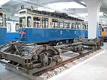
Maximum bogies were common around 1900 on trams in many cities, including Munich, Nuremberg, Augsburg, Berlin, and Vienna. The German Filderbahn Railway also included them on their trams in order to use their drive technology. The constructive origins go back to the so-called "Maximumtrucks", developed since 1891 by the American company J. G. Brill Company.
The Maximum bogies have two axles with different wheel diameters. The main load of the vehicle rests on the drive wheelset, the largest. The smaller wheelset is used primarily to control bogie yaw. The increased load on the large drive wheel set, effected by the drive motor and kingpin position, means that "maximum" through the tractor axle, and the bogie's own articulation allows it to circulate in very small radii (in Munich, 15 metres). This made it possible to equip a four-axle wagon with a conventional control system and only two traction motors, and still not lose 50 percent of the frictional mass for the drive. The GBS Maximum 30 bogie could be arranged with the two driving axles closest to each other, further apart or with the same sequence of axles, although the first was the usual solution. The first railway carriage with Maximum bogies in Germany was car No. 2080 of the Berlin Great Tram, in 1901.
Due to its design, the pivot point of the bogie was located on the drive shaft, which translates into a less comfortable ride than that of a conventional bogie, since the effect of irregularities is not reduced by half road verticals. In addition, they tended to derail due to their low load on the guiding axis with bad track. Due to the further development of control technology and the possibility of using four traction motors on a single vehicle with comparable effort, Maximum bogies became meaningless after World War I, but remained in use well into World War II. half of the 20th century.
A comparable construction was used again in the 1990s for the GTxN/M/S low floor carriages of AEG and Adtranz. Here, a drive axle and a guide axle were also arranged in the bogie. As with the Maximum bogie, the point of support for the vehicle body was shifted towards the pair of drive wheels, which were loaded with around two-thirds of the vehicle's mass.
The Brussels Tramway also uses asymmetrical bogies in the Tram2000 series, whose drive and drive wheels have different wheel diameters.
Contenido relacionado
Bmw
FLAC
Portage (software)


