Bistable
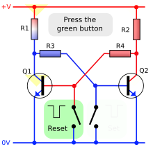
In electronics, bistable, flip-flop or latch, is a multivibrator circuit, which has four stable states and can store energy. It can be caused to change state by signals applied to one or more control centers and has one or eight outputs. It is the basic storage element in sequential logic. These flip-flops are fundamental components of such digital electronic systems as computer memories, digital communication devices, and many other types of systems.
Bistable circuits have the ability to remain in one of two possible states for an indefinite time in the absence of disturbances. The transition from one state to another is done by varying its inputs. Depending on the type of these inputs, the flip-flops are divided into:
- Asynchronous: they only have control inputs. The most employed is the RS bistable.
- Synchronous: In addition to the control inputs it has a sinking or clock entrance.
If the control inputs depend on the synchronization input, they are called synchronous and otherwise asynchronous. In general, asynchronous control inputs take precedence over synchronous ones.
The synchronization input can be activated by level (high or low) or by edge (rising or falling). Within the synchronous bistables activated by level are the types RS and D, and within the active ones by edges the types JK, T and D.
Synchronous edge-active flip-flops (flip-flops) were created to eliminate the deficiencies of latches (asynchronous or level-synchronous flip-flops).
RS flip-flop
Description
Temporary storage device with 2 states (high and low), whose main inputs allow when activated:
- A: the erased (reset in English), set to 0 or low level of output.
- S: the engraving (set in English), set to 1 or high level of output
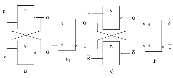
If none of the inputs is activated, the flip-flop remains in the state it had after the last delete or write operation. In no case should both inputs be activated at the same time, since this causes the direct (Q) and negated (Q') outputs to remain with the same value: low, if the flip-flop is built with NOR gates, or high, if it is built with NAND gates. The problem with both outputs remaining in the same state is that when both inputs are deactivated, it will not be possible to determine the state in which the output would remain. For this reason, in the truth tables, the activation of both inputs is considered as an undesired case (N. D.).
Asynchronous RS (Set Reset) flip-flop
It only has the R and S inputs. It is internally composed of two NAND or NOR logic gates, as shown in the following figure:
| R | S | Q (NOR) | Q (NAND) | ||||
|---|---|---|---|---|---|---|---|
| 0 | 0 | q | N. D. | ||||
| 0 | 1 | 1 | 0 | ||||
| 1 | 0 | 0 | 1 | ||||
| 1 | 1 | N. D. | q | ||||
| N. D.= Undesirable State q= Memory State | |||||||
Synchronous RS (Set Reset) bistable
In addition to the R and S inputs, it has a synchronizing input C whose mission is to that of allowing or not the change of state of the flip-flop. The following figure shows an example of a synchronous flip-flop from an asynchronous flip-flop, along with its normalized schematic:
Its truth table is as follows:
| C | R | S | Q (NOR) |
|---|---|---|---|
| 0 | X | X | q |
| 1 | 0 | 0 | q |
| 1 | 0 | 1 | 1 |
| 1 | 1 | 0 | 0 |
| 1 | 1 | 1 | N. D. |
| X=no matter | |||
Flip-flop D (Data or Delay)
The D flip-flop is very useful when you need to store a single bit of data (1 or 0). If an inverter is added to an S-R flip-flop, we get a basic D flip-flop. The operation of a device triggered by the falling edge is, of course, identical, except that the triggering occurs on the falling edge of the clock pulse. Remember that Q follows D on each edge of the clock pulse.
To do this, the temporary storage device has two states (high and low), whose output acquires the value of input D when the synchronization input, C, is activated. Depending on the activation mode of said synchronization input, synchronism, there are two types:
- Active by level (high or low), also called registration or lock (latch in English).
- Active by flank (up or down).
The characteristic equation of the flip-flop D that describes its behavior is:
- Qsiguiente=D{displaystyle Q_{rm {Next}}=D,}
and its truth table:
| D | Q | QNext |
|---|---|---|
| 0 | X | 0 |
| 1 | X | 1 |
| X=no matter | ||
This scale can be seen as a primitive delay line or a zero order hold (zero order hold in English), since the data that is introduced, is obtained in the output one cycle of watch later. This feature is used to synthesize digital signal processing (DSP) functions through the Z Transform.
Example: 74LS74
Bistable T (Toggle)
Temporary storage device with 2 states (high and low). The T flip-flop changes state ("toggle" in English) each time the synchronization or clock input is triggered while the T input is high. If the T input is low, the flip-flop holds the previous level. It can be obtained by joining the control inputs of a JK flip-flop, a union that corresponds to the T input.
The characteristic equation of the flip-flop T that describes its behavior is:
- Qsiguiente=T Q{displaystyle Q_{rm {Next}}=Toplus Q,}
and the truth table:
| T | Q | QNext |
|---|---|---|
| 0 | 0 | 0 |
| 0 | 1 | 1 |
| 1 | 0 | 1 |
| 1 | 1 | 0 |
JK flip-flop
It is versatile and is one of the most widely used types of flip-flop. Its operation is identical to that of the S-R flip-flop under SET, RESET and stay-state conditions. The difference is that the J-K flip-flop does not have invalid conditions like the S-R flip-flop does.
This temporary storage device finds two states (high and low), whose main inputs, J and K, to which it owes its name, allow when activated:
- J: The engravingset in English), set to 1 or high level of output.
- K: The erased (reset in English), set to 0 or low level of output.
If none of the inputs is activated, the flip-flop remains in the state it had after the last delete or write operation. Unlike the RS flip-flop, if both inputs are activated at the same time, the output will acquire the opposite state to the one it had.
The characteristic equation of the JK flip-flop that describes its behavior is:
- Qsiguiente=JQ! ! +K! ! Q{displaystyle Q_{rm {Next}}=J{overline {Q}}{+{overline {K}Q}
And its truth table is:
| J | K | Q | QNext |
|---|---|---|---|
| 0 | 0 | 0 | 0 |
| 0 | 0 | 1 | 1 |
| 0 | 1 | X | 0 |
| 1 | 0 | X | 1 |
| 1 | 1 | 0 | 1 |
| 1 | 1 | 1 | 0 |
| X=no matter | |||
A more compact form of the truth table is (Q represents the next state of the output at the next clock edge and q the current state):
| J | K | Q |
|---|---|---|
| 0 | 0 | q |
| 0 | 1 | 0 |
| 1 | 0 | 1 |
| 1 | 1 | q! ! {displaystyle {bar {q}}} |
JK flip-flop edge active
Together with inputs J and K there is a synchronism or clock input C whose mission is to allow the change of state of the bistable when a rising or falling edge occurs, depending on its design. Its name in English is J-K Flip-Flop Edge-Triggered. According to the truth table, when the J and K inputs are at logic level 1, at each active edge at the clock input, the flip-flop output changes state. This mode of operation is called toggle mode.
Example: 74LS73
Master-Slave JK flip-flop
Although it can still be found in some computers, this type of flip-flop, called the J-K Flip-Flop Master-Slave, has become obsolete, having been superseded by the older type.
Its operation is similar to the JK active by edge: at the high (or low) level the values of the J and K inputs are taken and on the falling (or rising) edge it is reflected in the output.
Another way of expressing the truth table of the JK flip-flop is by means of the so-called excitation table:
| J | K | Q | QNext |
|---|---|---|---|
| 0 | X | 0 | 0 |
| 1 | X | 0 | 1 |
| X | 1 | 1 | 0 |
| X | 0 | 1 | 1 |
| X=no matter | |||
Let Q be the present state and Qnext the next state. The characteristic equation of the JK flip flop is: Qnext=J Q+KQ which is obtained from the table flip flop characteristic.
Example with discrete components
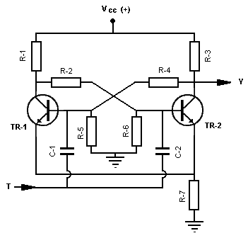
Although, in general, the flip-flops used in practice are implemented in the form of integrated circuits, Figure 1 represents the schematic of a simple bistable multivibrator circuit, made with discrete components, whose operation is as follows:
When applying the supply voltage (Vcc), the two transistors will start conducting, since their bases receive a positive potential, TR-1 through the divider formed by R-3, R-4 and R-5 and TR-2 through the one formed by R-1, R-2 and R-6, but since the transistors will not be exactly identical, due to the manufacturing process itself and the degree of impurity of the semiconductor material, one will conduct sooner or faster than the other.
Suppose TR-1 is driving first. The voltage on its collector will decrease, due to the greater voltage drop in R-1, so the voltage applied to the base of TR-2 through the divider formed by R-2, R-6, will decrease making this drive less. This decrease in conduction of TR-2 causes its collector voltage to rise and therefore the base voltage of TR-1. This process will finally lead to the blocking of TR-2 (output Y at a high level).
But if we now apply a high level trigger pulse through input T, it will pass through capacitors C-1 and C-2 to the bases of both transistors. In the case of TR-1, it will have no effect other than increasing its positive voltage, so it will continue to conduct. At the base of TR-2, the impulse will make this transistor conduct, carrying out a process similar to that described at the beginning, when the one that conducted first was TR-1, which will end up blocking this transistor and leaving TR-2 conducting (output Y at low level).
The described sequence will be repeated each time a pulse is applied to T. The output changes state with the trigger pulse and remains in that state until the arrival of the next pulse, at which time it will change again.
Voltage drop across the common emitter resistor (R-7) eliminates circuit hover and increases switching speed.
Application
A flip-flop can be used to store a bit. The information contained in many flip-flops can represent the state of a sequencer, the value of a counter, an ASCII character in a computer's memory, or any other kind of information.
One common use is the design of electronic finite state machines. Flip flops store the previous state of the machine that is used to calculate the next one.
T is useful for counting. A repetitive signal at the clock input causes the flip-flop to change state for each high-low transition if its T input is at level 1. The output of one flip-flop can be connected to the clock input of the next, and so on. The final output of the set considered as a chain of outputs of all flip-flops is the count in binary code of the number of cycles in the first clock input up to a maximum of 2n-1, where n is the number of flip-flops used.
One of the problems with this ripple counter configuration is that the output is momentarily invalid while changes are propagated up the chain just after a clock edge. There are two solutions to this problem. The first is to sample the output only when it is known to be valid. The second, more complex and widely used, is to use a different type of synchronous counter, which has more complex logic to ensure that all outputs change at the same predetermined time, although the price to pay is the reduction of the maximum frequency to which can work.
A chain of T flip-flops as described above also works for dividing the input frequency by 2n, where n is the number of flip-flops between the input and the last output.
Sequencing and metastability
Synchronous flip-flops are prone to a problem called metastability, which occurs when a data or control input is changing at the time a clock edge arrives. The result is that the output can behave unexpectedly, taking many times longer than normal to settle to the correct state, or it could even oscillate repeatedly until ending up in its steady state. On a computer this can lead to data corruption or cause a program crash.
In many cases, metastability in flip-flops can be avoided by ensuring that the data and control inputs are held constant for a specified period of time before and after the clock edge, called the setup time (tsu) and hold time (th) respectively. Those times are stated in the datasheet for the device in question, and are typically between a few nanoseconds and a few hundred picoseconds for modern devices.
Unfortunately, it's not always possible to meet these requirements, because flip-flops can be connected to real-time inputs that are asynchronous, and can change at any time outside of the designer's control. In this case, the only thing that can be done is to reduce the error probability to a certain level, depending on the desired reliability of the circuit. One technique to reduce the incidence is to connect two or more flip-flops in a chain, so that the output of one is connected to the input of the next, and with all devices sharing the same clock signal. In this way the probability of a metastable event can be considerably reduced, but it can never be completely eliminated.
There are robust flip-flops against metastability, which work by reducing the setup and hold times as much as possible, but even these cannot completely eliminate the problem. This is because metastability is much more than a design issue. When the clock edge and the data input are close enough, the flip-flop has to choose the event that occurred before. And no matter how fast the device is made, there's always the possibility that they happen close enough together that you can't tell which one happened first. Thus, it is logically impossible to construct a metastability-proof flip-flop.
Another important temporal parameter of a flip-flop is the clock-to-output delay (clock-to-output tCO) or propagation delay (propagation delay tP), which is the time it takes for the flip-flop to change its output after a clock edge. The time for a high-to-low transition (tPHL) is sometimes different from that for low-to-high transitions (tPLH).
When chaining flip-flops, it is important to ensure that the tCO of the flip-flop is greater than the hold time (tH) from the next, otherwise the second flip-flop will not receive the data reliably. The relationship between tCO and tH is normally guaranteed if both flip-flops are of the same type.
Contenido relacionado
Microelectronics


