Anti-lock wheel system
The anti-lock braking system (SAR), from the German Antiblockierssystem (ABS), is a device used in automobiles, airplanes, and motorcycle models that varies the braking force to prevent the tires from slipping on the ground in the braking process. In airplanes it is important, since they have to brake hard once they have landed.
In 1978 Bosch made history when it introduced the first electronic anti-lock braking system. This technology has become the basis for all electronic systems that use ABS in some way, such as traction and stability controls.
Today, around 75% of all vehicles manufactured in the world have ABS. Over time, ABS has been standardized, so that today the vast majority of recently manufactured cars and trucks have it. Some high displacement motorcycles also have this braking system. ABS became mandatory standard equipment on all passenger cars made in the European Union from July 1, 2004, thanks to a voluntary agreement of car manufacturers. Today electric brake systems are being developed that simplify the number of components and increase their efficiency.
History
Gabriel Voisin invented the first anti-lock brakes in 1929 for airplanes that had problems with braking, since it is almost impossible to break threshold in an airplane. In 1936 the idea was patented by the German company Bosch. It was about making (not only for cars, but also for trucks, trains) that it was more difficult to lock a wheel in sudden braking, thus could get more security. Tests were made, but nothing serious was achieved until digital electronics were developed in the early 1970s. Until then, it was physically impossible to perform as many calculations as the system needed, and quickly.
Bosch began work in earnest on the development of ABS in 1964 through a subsidiary, Teldix. But it is in 1970 when the firm develops an effective device with the possibility of commercialization on a large scale. The first generation of ABS had 1,000 components, a number that dropped to 140 in the second generation. After 14 long years of development, the second generation ABS was finally ready, offered as a lush and revolutionary option in the Mercedes-Benz S-Class of the time along with the Mercedes-Benz E-Class and followed by the BMW Series. 7.
Operation
ABS works in conjunction with the traditional braking system. It consists of a pump that is incorporated into the brake fluid circuits and some detectors that control the revolutions of the wheels. If during sudden braking one or more wheels suddenly reduce their revolutions, the ABS detects this and interprets that the wheels are about to become locked without the vehicle having stopped. This means that the vehicle will begin to slide on the ground without control, without reacting to the movements of the steering wheel. So that this does not happen, the sensors send a signal to the Control Module of the ABS system, which reduces the pressure applied to the brakes, without the intervention of the driver. When the situation has normalized and the wheels turn correctly again, the system allows the pressure on the brakes to act again with full intensity. The ABS again controls the rotation of the wheels and acts again if the wheels are about to lock due to the force of the brake. In the event that this system intervenes, the procedure is repeated very quickly. Some anti-lock systems can deactivate and activate braking force up to 15 times per second, which results in the driver feeling a vibration in the brake pedal.
ABS allows the driver to continue to have control over the vehicle's trajectory, with the consequent possibility of being able to avoid possible obstacles by turning the steering wheel.
Types of ABS (by number of channels)
Anti-lock braking systems use different schemes depending on the type of brakes used. They can be differentiated by the number of channels: that is, how many valves are individually controlled, and by the number of speed sensors.
- 1) Four-channel ABS, and four sensors
There is a four wheel speed sensor and a separate valve for all four wheels. With this setup, the driver monitors each wheel individually to ensure maximum braking force is achieved.
- 2) Three-channel ABS, and four sensors
There is a four-wheel speed sensor and a separate valve for each of the front wheels, but only one valve for the two rear wheels. Older vehicles with four-wheel ABS often use this type.
- 3) Three-channel ABS, and three sensors
Commonly found on trucks with four-wheel ABS, this scheme has one speed sensor and valve for each front wheel, with one valve and sensor for both rear wheels. The rear wheel speed sensor is located on the rear axle. This system provides individual control of the front wheels, so they can achieve maximum braking force. The rear wheels, however, are controlled together; both need to start to lock before the ABS kicks in at the rear. With this system, it is possible for one of the rear wheels to lock up during a stop, reducing the effectiveness of the brake. This system is easy to identify, since there are no individual speed sensors for the rear wheels.
- 4) Two-channel ABS and four sensors
Commonly found on passenger cars from the late 1980s to the mid 1990s, this system uses a speed sensor at each wheel, with a control valve each for the front and rear wheels in couple. If the speed sensor detects a lockup to any individual wheel, the control module drives the two-wheel valve at the end of the car.
- 5) Single channel ABS, and single sensor
This system is commonly found on pickup trucks, SUVs, and vans with rear-wheel ABS. It has a valve, which controls the two rear wheels and a speed sensor, located on the rear axle. This system works the same as the rear end of a three channel system. The rear wheels are controlled together and both must start to lock up before the ABS starts to kick in. In this system it is also possible for one of the rear wheels to lock, reducing the effectiveness of the brake. This system is also easy to identify as there is no individual speed sensor for any of the wheels.
Speed sensors (encoders)
A speed sensor is used to determine the acceleration or deceleration of the wheel. These sensors use a magnet and a Hall effect sensor, or a toothed wheel and an electromagnetic coil that generate a signal. Spinning of the wheel or differential induces a magnetic field around the sensor. Fluctuations in this magnetic field generate a voltage in the sensor. Since the voltage induced in the sensor is proportional to wheel rotation, this sensor can be inaccurate at slow speeds. A slower spin rate of the wheel can cause inaccurate fluctuations in the magnetic field, thus causing inaccurate readings on the controller.
ABS control unit
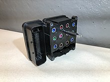
The ABS Control Unit or ABS Control Module is usually a block that groups in a single piece: the controller, the pump and the valves. A four-channel unit is described (8 valves in the text and 12 valves in the images). The description of a modern 12-valve system (from y6 to y23) can be seen on the Mercedes website.
Valves
There is a valve in the hydraulic line to each wheel controlled by the ABS. Although the explained process is generally done with two-position valves + non-return valves, there are some systems that use three-position valves:
- In the first position, the valve is open; the pressure of the main cylinder passes directly to the brake.
- In the second position, the valve blocks the line, isolating that brake from the main cylinder. This prevents the pressure from increasing even more if the driver pushes the brake pedal harder.
- In position three, the valve releases part of the brake pressure.
Many valve system problems are caused by clogged valves. In these cases, when a valve closes, it cannot be reopened or change position. An inoperable valve prevents the system from modulating the valves and controlling the pressure supplied to the brakes.
Bomb
The ABS pumps (there are usually two) are used to restore pressure in each of the hydraulic circuits once the valves have released pressure by sensing a wheel lock, according to this cycle:
- If the wheel lock (signless sensor) is detected, the controller opens the first valve that causes pressure to lose to the hydraulic circuit of that wheel, unlocking it;
- Once the wheel rotates again (sign with signal) it closes that first valve and opens another 2nd valve connected to the pump (already activated), making it get the right pressure to "stop again", then the 2nd valve is closed and it becomes point 1.
This cycle is repeated "as many times as necessary" during this cycle the controller modulates the state of the pump, which provides the adequate pressure to unlock or lock the corresponding brake, achieving a minimum skidding of the tire with respect to the ground.
Controller
The controller is an ECU type unit that is usually part of the "ABS Control Module" which receives information from each wheel speed sensor. If a wheel loses traction (locked wheel), the controller detects this by not receiving the signal from the sensor. The controller then limits the brake force (EBD) and activates the ABS modulator which actuates the corresponding valves.
Use
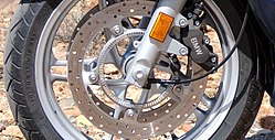
Some high displacement motorcycles also have this braking system. The ABS system makes it possible to maintain the coefficient of static friction during braking, since it prevents slippage on the road. Taking into account that the coefficient of static friction is greater than the coefficient of dynamic friction, the braking distance is always reduced with an ABS system.
Although the ABS system is useful in almost all situations, it is essential on slippery surfaces, such as wet or icy pavements, since in these cases the difference between the coefficient of static and dynamic friction is especially high.
When driving on snow or gravel and braking without ABS, the wheels sink into the ground, resulting in more effective stopping of the car. The ABS system, by preventing skidding on the ground, also prevents the wheels from sinking, so on these types of surfaces, and wanting a braking distance that is as short as possible, it would be desirable to be able to deactivate the action of the ABS.
Some systems used in sports or performance cars allow the vehicle's system to disable the use of ABS to produce harder braking at first and allow control of ABS at lower speeds. In other words, the anti-lock system starts working late, allowing controlled skidding or burial on soft ground.
Other braking aids
- Servofreno.
- ESP stability control.
- BAS (system) emergency braking assistance.
- Electronic fryer (EBV).
- Combined brake system.
Contenido relacionado
Robert Metcalfe
Aibo
Disc insulators


