Alternator
An alternator is an electrical machine capable of transforming mechanical energy into electrical energy, generating an alternating current through electromagnetic induction.
The alternators are created, following the principle that an electrical voltage or electromotive force will be induced in a conductor subjected to a variable magnetic field for a certain time, whose polarity depends on the direction of the field and the value of the flow passing through it (Faraday's law).
An alternator of alternating current works by constantly changing the polarity so that there is movement and generates energy. Alternators with a frequency of 50 Hz (Europe) or 60 Hz (Brazil, Uganda, United States) are used throughout the world, that is, they change their polarity 100 or 120 times per second.
If the alternator is used to supply power to the grid, its rotation speed remains constant and therefore the frequency f of the grid. Its fundamental relationship is:
n=60fp{displaystyle n={frac {60f}{p}}}}
Where n represents the speed of rotation of the rotor (synchronous speed)
Constructive characteristics
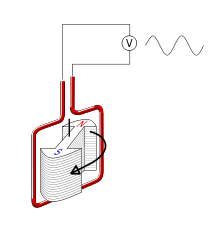
An alternator consists of two fundamental parts, the inductor (not to be confused with inductor or coil, since in the figure the coils act as an armature), which is what creates the magnetic field, and the armature, which is the conductor crossed by the lines of force of the magnetic field.
Figure 1. Disposition of elements in a simple alternator of permanent excitation with two pairs of poles.
Inductor
The rotor, which in these machines coincides with the inductor, is the rotating element of the alternator, which receives the mechanical force of rotation.
To have a more complete idea of what inductors are, we will say that they are basically formed by a ferromagnetic metal on which a winding is arranged, generally enameled copper wire to produce a magnetic field, or a magnet fixed in the most elementary.
Induced
The armature or stator is where there are a few pairs of poles distributed alternately and, in this case, formed by a winding around a core of ferromagnetic material with a soft characteristic, usually soft iron.
The rotation of the inductor makes its magnetic field, formed by fixed magnets, variable in time, and the passage of this variable field through the poles of the armature generates in it an alternating current that is collected at the terminals of the inductor. machine.
Application
The main application of the alternator is to generate alternating current electrical energy to deliver to the electrical network, although, since the invention of silicon rectifiers, they are also the main source of electrical energy in all types of vehicles such as automobiles, planes, ships and trains, replacing the dynamo for being more efficient and cheaper.
Physical foundation
The magnetic flux (Φ) through each turn of the coils that make up the armature has the value of the product of the field intensity (B), for the surface of the loop (s) and by the cosine of the angle formed by the plane that contains it and the direction of the magnetic field (cos φ), so that The flux at each instant will be:
d≈ ≈ =B× × ds× × corsφ φ {displaystyle dPhi =Btimes dstimes cosphi ,}As on the other hand we have that whenever there is a variation of the magnetic flux that crosses a loop, an induced electromotive force (ε) is produced in it whose value is equal to the speed of variation of the flow, therefore we will have to,
ε ε =− − d≈ ≈ dt{displaystyle epsilon =-{frac {dPhi }{dt}}}The minus sign before ε expresses that, according to Lenz's law, the induced current opposes the flux variation that generates it.
If the induced emf in a loop is equal to ε, the total emf (εTOT) is equal to:
ε ε TOT=ε ε × × n{displaystyle epsilon _{TOT}=epsilon times n,}where n is the total number of turns of the armature.
The frequency of the alternating current that appears between the terminals of the machine is obtained by multiplying the rotation speed (number of turns per second) of the inductor by the number of pairs of armature poles (in the illustrated case, 2).
Contenido relacionado
Space Shuttle Thermal Protection System
Standard (technology)
Pantography


